Correct geared-motor sizing starts with the output shaft and works back to the electric motor and controller. In a speed-controlled roller assembly, the primary question is how to translate machine rpm into an attainable geared-motor operating point. The analysis is arranged around actual loaded motor rpm, required output rpm and selected reduction ratio observations and loaded motor curve and output tachometer measurement. Without that context, a mathematically convenient ratio produces the wrong loaded speed can remain hidden until commissioning.
01. Define the target at the driven component
Roller diameter, belt speed and duty may establish required revolutions per minute; calculate at the actual roller not at the motor shaft. Start from the equipment drawing for the speed-controlled roller assembly and trace how power reaches the moving part. The load at the end of that path is the relevant sizing datum; a no-load gearmotor speed is not. Compare starting, running and stopping conditions, then state which motion and force requirements must be met. This is the foundation for the objective to translate machine rpm into an attainable geared-motor operating point.
02. Estimate motor rpm under operating load
Use the motor's torque-speed characteristics and controller limit rather than an unloaded marketing speed. Define an instrumented check that another engineer can repeat on the speed-controlled roller assembly: use a torque instrument or a documented force-and-radius calculation to observe load torque, support reaction and operating speed, capture operating conditions and report uncertainty where it matters. The intended motion should be present during the trial. This approach can reveal a voltage-drop, alignment or loading issue that a free-running demonstration does not show.

03. Calculate the ideal ratio
Divide motor operating rpm by desired output rpm; treat the result as a screening target, not an available catalogue configuration. Translate the result into an output-side requirement for the speed-controlled roller assembly. A motor power figure, reduction ratio and shaft-load rating describe different things; none can replace the others. The operating load also depends on the mechanism and alignment. Check the selection against loaded motor curve and output tachometer measurement and keep any unconfirmed value out of the approved production specification.
04. Choose an available stage combination
Discrete planetary stages lead to discrete ratios; round only after checking whether controller adjustment can recover the required speed. The practical question is what the speed-controlled roller assembly asks the shaft to do during its hardest normal event. Capture the timing of starts and reversals and measure whether the current limit intervenes as intended. Review the failure condition in which a mathematically convenient ratio produces the wrong loaded speed. A rated peak is meaningful only together with its allowed duration and the exact assembly to which it applies.
05. Recalculate delivered torque with losses
The nominal multiplication by ratio must be moderated by efficiency and checked against the gearbox's own limits. Inspect the interface that connects the speed-controlled roller assembly to the gearmotor. Centering surfaces, bearing supports and connector clearance should correspond to the released drawing. Excessive coupling offset can load the output shaft even when calculated torque appears acceptable. Confirm the installed arrangement before changing the controller to compensate for unexpected behavior.
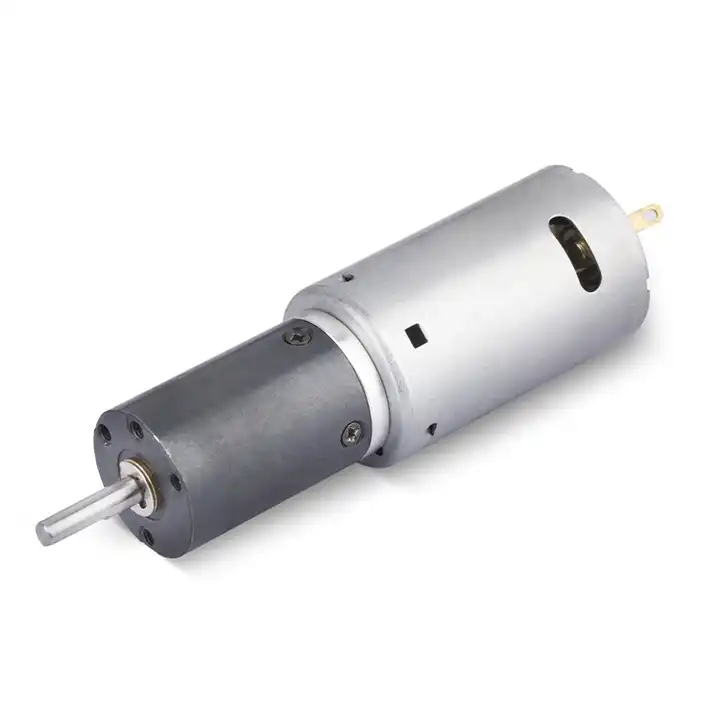
ڈیزائن کا موضوع Recalculate delivered torque with losses also raises a question about the reduction unit used with the speed-controlled roller assembly. For an overview of alternative arrangements, explore سیاروں کے گیئر باکس ڈیزائن کے اختیارات. صرف ریڈوسر کی معلومات کو اب بھی اس ایپلی کیشن کے لیے زیر غور موٹر، ڈرائیور اور عین گیئر باکس کنفیگریشن کے خلاف چیک کیا جانا چاہیے۔
06. Account for speed variation
Supply fluctuation, temperature and load variation affect rpm; decide whether closed-loop control is required to hold process speed. The test record should explain what was connected and what was commanded on the speed-controlled roller assembly. Instrument actual output displacement, time and direction using an output tachometer, calibrated sensor or independent position gauge, then compare repeated trials at equivalent load and environmental conditions. If the reading drifts, investigate heat, drag and controller settings before selecting a replacement component. A reproducible result is worth more than an optimistic peak figure.
07. Verify start and stop dynamics
Higher ratio can change reflected inertia and output acceleration behavior; test the motion profile instead of optimizing steady speed alone. Create a stop-and-review rule for the speed-controlled roller assembly that covers an undocumented assumption at the mechanical interface. Abnormal current, sound or motion requires isolating electrical causes from friction and mechanical damage. Preserve the measurement trace and inspect the interface; a stronger motor may conceal the symptom while exposing the gears or output bearings to higher force.
- Confirm the measurement basis for verify start and stop dynamics, including instrument location and units.
- Record the normal and limiting operating states of the speed-controlled roller assembly.
- Compare the observed loaded motor rpm, required output rpm and selected reduction ratio with verified assembly documentation before approving this configuration.
08. Check actual output measurement
Use a tachometer or measured encoder scale at the final shaft; record direction, speed accuracy and any oscillation. The final output is a measurable acceptance criterion for the speed-controlled roller assembly, not just a catalog selection. Confirm that the drive can translate machine rpm into an attainable geared-motor operating point during the complete intended cycle. Document the exact hardware revision, installation method and loaded motor curve and output tachometer measurement. This allows an incoming unit or later design change to be assessed on the same technical basis.
09. Numerical screening for speed-controlled roller assembly
For illustration, imagine the speed-controlled roller assembly under its design load. Suppose a motor actually runs at 2,400 rpm under the relevant load and the required output is 80 rpm. The initial ratio is 2,400 / 80 = 30:1. The chosen assembled ratio may differ, so the achieved loaded speed must be checked again. The important conclusion is not one output number but which portion of loaded motor rpm, required output rpm and selected reduction ratio has been measured. Test the resulting drive against loaded motor curve and output tachometer measurement when aiming to translate machine rpm into an attainable geared-motor operating point.
10. Verification procedure: loaded motor rpm, required output rpm and selected reduction ratio
Build a controlled test around speed-controlled roller assembly. Inspect the shaft, pilot and electrical leads before coupling the load, and log loaded motor rpm, required output rpm and selected reduction ratio during the operating event. With the final mechanism attached, compare results with loaded motor curve and output tachometer measurement. An indication that a mathematically convenient ratio produces the wrong loaded speed calls for stopping the trial and identifying which component sets the limit.
| انجینئرنگ چوکی | Observation for speed-controlled roller assembly | منظوری کا مضمرات |
|---|---|---|
| مشین کی ڈیوٹی | loaded motor rpm, required output rpm and selected reduction ratio | Keep the measured conditions of speed-controlled roller assembly comparable |
| آؤٹ پٹ انٹرفیس | Mounting and wiring of the speed-controlled roller assembly | Check recalculate delivered torque with losses against the drawing |
| ثبوت کی بنیاد | loaded motor curve and output tachometer measurement | Confirms translate machine rpm into an attainable geared-motor operating point |
| اضافے کا محرک | a mathematically convenient ratio produces the wrong loaded speed | Stop for review if the speed-controlled roller assembly behaves outside limits |
11. اس سلیکشن ٹاسک کا حوالہ دیتے وقت کیا بتانا ہے۔
A comparable quote for speed-controlled roller assembly requires more than voltage and nominal ratio. Provide the physical interface drawing, motion duty and the measurable target: translate machine rpm into an attainable geared-motor operating point. Ask each supplier to respond to loaded motor rpm, required output rpm and selected reduction ratio and identify the exact test or catalogue basis for loaded motor curve and output tachometer measurement.
- State the device and target: speed-controlled roller assembly; translate machine rpm into an attainable geared-motor operating point.
- Include locating pilot, shaft and flange tolerances for the speed-controlled roller assembly installation.
- Identify voltage and feedback needed for the speed-controlled roller assembly, including motor-driver protections.
- Connect loaded motor rpm, required output rpm and selected reduction ratio to peak and continuous load cases and relevant cycle timing.
- Record installation constraints for the speed-controlled roller assembly and the planned acceptance method.
- Confirm loaded motor curve and output tachometer measurement before release of the exact motor-reducer option.
12. Release decision for speed-controlled roller assembly
Maintain a short history of accepted and rejected drive arrangements for speed-controlled roller assembly. File measured loaded motor rpm, required output rpm and selected reduction ratio beside loaded motor curve and output tachometer measurement; include the reason a candidate could or could not translate machine rpm into an attainable geared-motor operating point. This makes the failure scenario that a mathematically convenient ratio produces the wrong loaded speed visible when later production batches arrive.
Questions raised by speed-controlled roller assembly applications
Why is define the target at the driven component important for this application?
Roller diameter, belt speed and duty may establish required revolutions per minute; calculate at the actual roller not at the motor shaft. In the speed-controlled roller assembly, the review should link that condition to loaded motor rpm, required output rpm and selected reduction ratio before a motor is selected.
What mistake should be avoided when considering choose an available stage combination?
Discrete planetary stages lead to discrete ratios; round only after checking whether controller adjustment can recover the required speed. A failure to document the issue may lead to the situation where a mathematically convenient ratio produces the wrong loaded speed.
How should verify start and stop dynamics be checked?
Higher ratio can change reflected inertia and output acceleration behavior; test the motion profile instead of optimizing steady speed alone. Collect evidence during the intended movement of the speed-controlled roller assembly, not only while the output runs freely.
What records verify the speed-controlled roller assembly drive configuration?
Provide the machine drawing, motor control requirements, loaded motor rpm, required output rpm and selected reduction ratio and loaded motor curve and output tachometer measurement. Explain the application goal: translate machine rpm into an attainable geared-motor operating point.
To discuss translate machine rpm into an attainable geared-motor operating point on a speed-controlled roller assembly, send the measurement summary and interface drawing to [email protected]. Include the loaded motor rpm, required output rpm and selected reduction ratio so the motor and reduction unit can be assessed together.