The final load defines the drive. Application geometry can change the required output torque more than a change of motor size. Consider an industrial airflow damper adjustment that must match low-speed travel and end-stop torque to valve friction and safety. Its motor and reduction unit must be treated together with the supporting hardware and controller. The risk that a motor sized for normal running cannot break free a sticky actuator frames the checks in this article; valve turning torque, travel angle, seal friction and actuation time are part of the necessary evidence.
01. Characterize the damper torque curve
Seal friction, aerodynamic pressure and linkage geometry can change resisting torque over the travel angle. Start from the equipment drawing for the industrial airflow damper adjustment and trace how power reaches the moving part. The load at the end of that path is the relevant sizing datum; a no-load gearmotor speed is not. Compare starting, running and stopping conditions, then state which motion and force requirements must be met. This is the foundation for the objective to match low-speed travel and end-stop torque to valve friction and safety.
02. Convert travel angle to motor movement
Quarter-turn and multi-turn mechanisms impose different output shaft revolutions and possible reducer stage requirements. Define an instrumented check that another engineer can repeat on the industrial airflow damper adjustment: use an output tachometer, calibrated sensor or independent position gauge to observe actual output displacement, time and direction, capture operating conditions and report uncertainty where it matters. The intended motion should be present during the trial. This approach can reveal a voltage-drop, alignment or loading issue that a free-running demonstration does not show.
03. Pay attention to breakaway torque
After long idle periods, seals can stick; a safe drive should detect and handle the increased initial load. Translate the result into an output-side requirement for the industrial airflow damper adjustment. A motor power figure, reduction ratio and shaft-load rating describe different things; none can replace the others. The operating load also depends on the mechanism and alignment. Check the selection against maximum differential pressure and cold-start test and keep any unconfirmed value out of the approved production specification.
04. Avoid damaging end stops
Limit switches or measured angle should terminate travel before repeated mechanical impact; use bounded torque protection. A successful single start does not validate a production cycle for the industrial airflow damper adjustment. Record the peak load, the length of the event and the interval before it recurs. The design review must specifically address the possibility that a motor sized for normal running cannot break free a sticky actuator. A protected repeat-cycle trial is more informative than repeating one unloaded startup.
05. Decide what happens on power loss
Some systems require spring return, fail-open or fail-closed behavior, which a gear motor alone may not provide. Inspect the interface that connects the industrial airflow damper adjustment to the gearmotor. Centering surfaces, bearing supports and connector clearance should correspond to the released drawing. Excessive coupling offset can load the output shaft even when calculated torque appears acceptable. Confirm the installed arrangement before changing the controller to compensate for unexpected behavior.

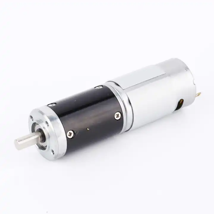
The design topic Decide what happens on power loss also raises a question about the reduction unit used with the industrial airflow damper adjustment. For an overview of alternative arrangements, explore a wider range of planetary gearboxes. Reducer-only information must still be checked against the motor, driver and exact gearbox configuration considered for this application.
06. Check shaft and coupling backlash
A loose linkage can cause deadband during small position commands even when the motor encoder shows movement. Qualify the proposed drive in the machine configuration that will actually be used. With the industrial airflow damper adjustment loaded, observe load torque, support reaction and operating speed using a torque instrument or a documented force-and-radius calculation and retain the operating trace. Repeat the cycle long enough to expose a stable temperature trend where appropriate. The result must be assessed against agreed criteria, not against an informal impression that the motor feels satisfactory.
07. Plan for environmental exposure
Dust, humidity, elevated temperature and outdoor condensation determine sealing and connector requirements. Define the conditions that require the industrial airflow damper adjustment test to stop. A finding of an undocumented assumption at the mechanical interface should trigger a check of shaft support, wiring and the commanded motion profile. Keep the duty and environment unchanged while testing one possible cause at a time. This protects the unit and produces evidence that is useful for engineering or supplier follow-up.
- Confirm the measurement basis for plan for environmental exposure, including instrument location and units.
- Record the normal and limiting operating states of the industrial airflow damper adjustment.
- Compare the observed valve turning torque, travel angle, seal friction and actuation time with verified assembly documentation before approving this configuration.
08. Test under process conditions
Verify travel time, holding behavior and peak current at the highest expected differential pressure and temperature extremes. Close the engineering review by linking observed machine behavior to documented component limits. The industrial airflow damper adjustment must match low-speed travel and end-stop torque to valve friction and safety without exceeding the ratings of its motor, gearhead or mechanical interfaces. Keep maximum differential pressure and cold-start test with the relevant test report. Reopen the decision when the duty profile, applied load or wiring is changed.

09. Numerical screening for industrial airflow damper adjustment
A worked example helps expose hidden assumptions in industrial airflow damper adjustment drive decisions. A force of 50 N acting at an effective 20 mm lever arm produces a simple torque of 1 N m before linkage and gear losses. The force profile may vary over the stroke; verify the maximum operating requirement at the least favorable position. Translate that calculation into a practical check of valve turning torque, travel angle, seal friction and actuation time. The result supports initial screening only; maximum differential pressure and cold-start test is still needed for a verified assembly.
10. Verification procedure: valve turning torque, travel angle, seal friction and actuation time
A repeatable functional check for industrial airflow damper adjustment should specify orientation, installed payload, bus supply and software revision. Observe valve turning torque, travel angle, seal friction and actuation time during movement and dwell. Evaluate maximum differential pressure and cold-start test in the same conditions; a mismatch that suggests a motor sized for normal running cannot break free a sticky actuator is a recorded engineering finding, not a minor cosmetic difference.
| Engineering checkpoint | Observation for industrial airflow damper adjustment | Approval implication |
|---|---|---|
| Machine duty | valve turning torque, travel angle, seal friction and actuation time | Keep the measured conditions of industrial airflow damper adjustment comparable |
| Output interface | Mounting and wiring of the industrial airflow damper adjustment | Check decide what happens on power loss against the drawing |
| Evidence basis | maximum differential pressure and cold-start test | Confirms match low-speed travel and end-stop torque to valve friction and safety |
| Escalation trigger | a motor sized for normal running cannot break free a sticky actuator | Stop for review if the industrial airflow damper adjustment behaves outside limits |
11. What to specify when quoting this application task
When requesting a design review for industrial airflow damper adjustment, state the requirement to match low-speed travel and end-stop torque to valve friction and safety in machine terms. Include drawings, shaft fit, mounting envelope, driver wiring and the expected operating cycle. Attach valve turning torque, travel angle, seal friction and actuation time from the current prototype when available, then request maximum differential pressure and cold-start test for the proposed full motor-and-gearbox combination.
- State the device and target: industrial airflow damper adjustment; match low-speed travel and end-stop torque to valve friction and safety.
- Include locating pilot, shaft and flange tolerances for the industrial airflow damper adjustment installation.
- Identify voltage and feedback needed for the industrial airflow damper adjustment, including motor-driver protections.
- Connect valve turning torque, travel angle, seal friction and actuation time to peak and continuous load cases and relevant cycle timing.
- Record installation constraints for the industrial airflow damper adjustment and the planned acceptance method.
- Confirm maximum differential pressure and cold-start test before release of the exact motor-reducer option.
12. Release decision for industrial airflow damper adjustment
Final acceptance of an industrial airflow damper adjustment drive is a traceable engineering decision, not an impression about compactness. The record should identify valve turning torque, travel angle, seal friction and actuation time, the selected component revision and maximum differential pressure and cold-start test. A change affecting the goal to match low-speed travel and end-stop torque to valve friction and safety reopens the mechanical and electrical checks.
Questions raised by industrial airflow damper adjustment applications
Why is characterize the damper torque curve important for this application?
Seal friction, aerodynamic pressure and linkage geometry can change resisting torque over the travel angle. In the industrial airflow damper adjustment, the review should link that condition to valve turning torque, travel angle, seal friction and actuation time before a motor is selected.
What mistake should be avoided when considering avoid damaging end stops?
Limit switches or measured angle should terminate travel before repeated mechanical impact; use bounded torque protection. A failure to document the issue may lead to the situation where a motor sized for normal running cannot break free a sticky actuator.
How should plan for environmental exposure be checked?
Dust, humidity, elevated temperature and outdoor condensation determine sealing and connector requirements. Collect evidence during the intended movement of the industrial airflow damper adjustment, not only while the output runs freely.
What records verify the industrial airflow damper adjustment drive configuration?
Provide the machine drawing, motor control requirements, valve turning torque, travel angle, seal friction and actuation time and maximum differential pressure and cold-start test. Explain the application goal: match low-speed travel and end-stop torque to valve friction and safety.
To discuss match low-speed travel and end-stop torque to valve friction and safety on a industrial airflow damper adjustment, send the measurement summary and interface drawing to продажі@planetarymotors.top. Include the valve turning torque, travel angle, seal friction and actuation time so the motor and reduction unit can be assessed together.