A meaningful comparison holds the machine requirement constant while examining the complete drive assembly. Consider a mobile electromechanical device that must select supply voltage without confusing voltage with gearbox torque. Its motor and reduction unit must be treated together with the supporting hardware and controller. The risk that wiring and driver current become bottlenecks during acceleration frames the checks in this article; DC bus voltage, operating current and wiring voltage drop are part of the necessary evidence.
01. Voltage is a system decision
The required machine power and existing bus architecture establish the comparison; choosing 24V does not automatically double rated output torque. For the mobile electromechanical device, sketch the motion path before looking at a product list. Mark the moving mass, friction points, external forces and positions where the mechanism can bind. Identify what happens just before motion starts and just after it ends. Those events often matter more than a nominal motor-power label when the goal is to select supply voltage without confusing voltage with gearbox torque.
02. Estimate input current carefully
For the same electrical power, a higher supply voltage generally means lower current; winding designs and efficiencies must be compared rather than assuming interchangeable motors. Set up one repeatable operating point on the mobile electromechanical device. Record the applied load and supply conditions, then collect terminal voltage, current waveform and controller state. The practical measurement method is a current probe and a logged supply-voltage channel; retain a trace rather than only a pass/fail statement. This distinguishes a controller limit from resistance in the attached mechanism and makes later comparisons between candidates meaningful.

03. Assess voltage drop in the harness
Long small-gauge leads and connectors can reduce voltage at the motor terminals under load; measure drop during an actual startup event. Translate the result into an output-side requirement for the mobile electromechanical device. A motor power figure, reduction ratio and shaft-load rating describe different things; none can replace the others. The operating load also depends on the mechanism and alignment. Check the selection against complete supply and harness voltage budget and keep any unconfirmed value out of the approved production specification.
04. Recheck motor winding and speed
A motor rated for 12V must not be treated as a 24V device; nominal voltage affects speed constant and heating for a given winding. A successful single start does not validate a production cycle for the mobile electromechanical device. Record the peak load, the length of the event and the interval before it recurs. The design review must specifically address the possibility that wiring and driver current become bottlenecks during acceleration. A protected repeat-cycle trial is more informative than repeating one unloaded startup.
05. Size protection and switching
Relays, MOSFETs, fuses and cable insulation need ratings for steady current, startup pulses and inductive transients. The mobile electromechanical device can impose forces that a free gearmotor does not experience. Check the position of external supports, the coupling type and the path taken by mechanical reactions. Also look at cable routing through the intended motion range. A repeatable change after installation points toward a machine-interface issue that needs resolving at its source.

06. Consider battery operating range
An energy storage system varies with charge and load; set low-voltage behavior and controller cutoff with the battery chemistry in mind. For the mobile electromechanical device, write an acceptance procedure that can be run again after a design revision. The procedure should log terminal voltage, current waveform and controller state, measured through a current probe and a logged supply-voltage channel, together with software and wiring configuration. Observe both cold startup and a representative warm operating condition. Keep the outcome connected to the exact tested gearbox and motor revision.
07. Keep the reduction stage unchanged only when verified
An apparently similar gearhead can have different permitted input speed or motor pinion; verify assembled part numbers. Create a stop-and-review rule for the mobile electromechanical device that covers a change in sound or free movement after installation. Abnormal current, sound or motion requires isolating electrical causes from friction and mechanical damage. Preserve the measurement trace and inspect the interface; a stronger motor may conceal the symptom while exposing the gears or output bearings to higher force.
- Confirm the measurement basis for keep the reduction stage unchanged only when verified, including instrument location and units.
- Record the normal and limiting operating states of the mobile electromechanical device.
- Compare the observed DC bus voltage, operating current and wiring voltage drop with verified assembly documentation before approving this configuration.
08. Qualify at both electrical extremes
Run low-bus-start and high-bus-temperature checks with the normal mechanism connected, including abrupt stops and reversals. Close the engineering review by linking observed machine behavior to documented component limits. The mobile electromechanical device must select supply voltage without confusing voltage with gearbox torque without exceeding the ratings of its motor, gearhead or mechanical interfaces. Keep complete supply and harness voltage budget with the relevant test report. Reopen the decision when the duty profile, applied load or wiring is changed.
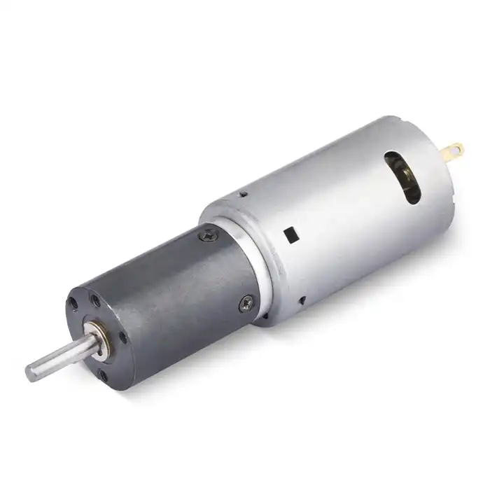
09. Numerical screening for mobile electromechanical device
A worked example helps expose hidden assumptions in mobile electromechanical device drive decisions. Consider an illustrative electrical demand of 120 W. Ignoring losses, a 12 V supply would carry 10 A, while a 24 V supply would carry 5 A. This is a wiring comparison, not a statement about any specific motor winding or allowable current. Translate that calculation into a practical check of DC bus voltage, operating current and wiring voltage drop. The result supports initial screening only; complete supply and harness voltage budget is still needed for a verified assembly.
10. Verification procedure: DC bus voltage, operating current and wiring voltage drop
A repeatable functional check for mobile electromechanical device should specify orientation, installed payload, bus supply and software revision. Observe DC bus voltage, operating current and wiring voltage drop during movement and dwell. Evaluate complete supply and harness voltage budget in the same conditions; a mismatch that suggests wiring and driver current become bottlenecks during acceleration is a recorded engineering finding, not a minor cosmetic difference.
| Engineering checkpoint | Observation for mobile electromechanical device | Approval implication |
|---|---|---|
| Machine duty | DC bus voltage, operating current and wiring voltage drop | Keep the measured conditions of mobile electromechanical device comparable |
| Output interface | Mounting and wiring of the mobile electromechanical device | Check size protection and switching against the drawing |
| Evidence basis | complete supply and harness voltage budget | Confirms select supply voltage without confusing voltage with gearbox torque |
| Escalation trigger | wiring and driver current become bottlenecks during acceleration | Stop for review if the mobile electromechanical device behaves outside limits |
11. What to specify when quoting this comparison task
When requesting a design review for mobile electromechanical device, state the requirement to select supply voltage without confusing voltage with gearbox torque in machine terms. Include drawings, shaft fit, mounting envelope, driver wiring and the expected operating cycle. Attach DC bus voltage, operating current and wiring voltage drop from the current prototype when available, then request complete supply and harness voltage budget for the proposed full motor-and-gearbox combination.
- State the device and target: mobile electromechanical device; select supply voltage without confusing voltage with gearbox torque.
- Include locating pilot, shaft and flange tolerances for the mobile electromechanical device installation.
- Identify voltage and feedback needed for the mobile electromechanical device, including motor-driver protections.
- Connect DC bus voltage, operating current and wiring voltage drop to peak and continuous load cases and relevant cycle timing.
- Record installation constraints for the mobile electromechanical device and the planned acceptance method.
- Confirm complete supply and harness voltage budget before release of the exact motor-reducer option.
12. Release decision for mobile electromechanical device
Final acceptance of a mobile electromechanical device drive is a traceable engineering decision, not an impression about compactness. The record should identify DC bus voltage, operating current and wiring voltage drop, the selected component revision and complete supply and harness voltage budget. A change affecting the goal to select supply voltage without confusing voltage with gearbox torque reopens the mechanical and electrical checks.
Questions raised by mobile electromechanical device applications
Why is voltage is a system decision important for this application?
The required machine power and existing bus architecture establish the comparison; choosing 24V does not automatically double rated output torque. In the mobile electromechanical device, the review should link that condition to DC bus voltage, operating current and wiring voltage drop before a motor is selected.
What mistake should be avoided when considering recheck motor winding and speed?
A motor rated for 12V must not be treated as a 24V device; nominal voltage affects speed constant and heating for a given winding. A failure to document the issue may lead to the situation where wiring and driver current become bottlenecks during acceleration.
How should keep the reduction stage unchanged only when verified be checked?
An apparently similar gearhead can have different permitted input speed or motor pinion; verify assembled part numbers. Collect evidence during the intended movement of the mobile electromechanical device, not only while the output runs freely.
What records verify the mobile electromechanical device drive configuration?
Provide the machine drawing, motor control requirements, DC bus voltage, operating current and wiring voltage drop and complete supply and harness voltage budget. Explain the application goal: select supply voltage without confusing voltage with gearbox torque.
To discuss select supply voltage without confusing voltage with gearbox torque on a mobile electromechanical device, send the measurement summary and interface drawing to продажі@planetarymotors.top. Include the DC bus voltage, operating current and wiring voltage drop so the motor and reduction unit can be assessed together.