The most expensive problems often arise at the interface between a healthy gearmotor and the machine around it. In a brushed DC gearmotor test fixture, the primary question is how to control speed and reversal while protecting the output transmission. The analysis is arranged around actual startup current, PWM switching frequency and stopping mode observations and current-limited acceleration and reverse tests. Without that context, an H-bridge is selected only by the motor's nominal current can remain hidden until commissioning.
01. Specify current in real operating states
Starting, running, blocked-rotor and reversal currents differ; the electronics must handle foreseeable peaks under protection rules. Start from the equipment drawing for the brushed DC gearmotor test fixture and trace how power reaches the moving part. The load at the end of that path is the relevant sizing datum; a no-load gearmotor speed is not. Compare starting, running and stopping conditions, then state which motion and force requirements must be met. This is the foundation for the objective to control speed and reversal while protecting the output transmission.
02. Understand PWM at the winding
Duty cycle changes effective applied voltage in common drive configurations, but motor inductance, frequency and recirculation path influence current ripple. Do not blend bench readings with machine readings. The brushed DC gearmotor test fixture has a particular drive installation and mechanical resistance, so measure terminal voltage, current waveform and controller state with a current probe and a logged supply-voltage channel after the coupling is installed. Note test speed, load and ambient temperature. Compare results to the original expectation and investigate discrepancies before increasing the motor or gearbox size.
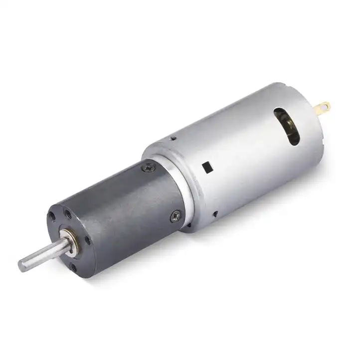
03. Command safe direction changes
Reversing bridge polarity at high speed can create large current and gear shock; define ramp-down and braking behavior. Use the measured output of the brushed DC gearmotor test fixture to challenge the proposed drive choice. Calculate the needed motion, account for efficiency where specified and check the physical shaft reaction. The objective to control speed and reversal while protecting the output transmission can be achieved only if the motor, reduction unit and controller each remain inside their individual ratings. Confirm those boundaries using current-limited acceleration and reverse tests.
04. Choose a braking mode deliberately
Coasting, short-circuit dynamic braking and regenerative options change stopping motion and energy flow; they are not interchangeable. The practical question is what the brushed DC gearmotor test fixture asks the shaft to do during its hardest normal event. Capture the timing of starts and reversals and measure whether the current limit intervenes as intended. Review the failure condition in which an H-bridge is selected only by the motor's nominal current. A rated peak is meaningful only together with its allowed duration and the exact assembly to which it applies.
05. Use feedback when repeatable speed matters
Open-loop PWM cannot guarantee identical speed as battery voltage or load changes; measured rpm enables regulation. The brushed DC gearmotor test fixture can impose forces that a free gearmotor does not experience. Check the position of external supports, the coupling type and the path taken by mechanical reactions. Also look at cable routing through the intended motion range. A repeatable change after installation points toward a machine-interface issue that needs resolving at its source.
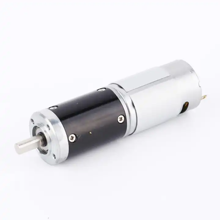
06. Check switching noise and heating
Cable layout, grounding, diode paths and device losses influence reliability and electromagnetic compatibility. For the brushed DC gearmotor test fixture, write an acceptance procedure that can be run again after a design revision. The procedure should log cycle duration, case temperature and surrounding air temperature, measured through a repeatable duty-cycle test with temperature logging, together with software and wiring configuration. Observe both cold startup and a representative warm operating condition. Keep the outcome connected to the exact tested gearbox and motor revision.
07. Protect against sustained stall
A gearhead can be damaged by a high stall torque even when the motor and bridge tolerate short current spikes. When the brushed DC gearmotor test fixture shows signs of an undocumented assumption at the mechanical interface, investigate before escalating the motor rating. Check whether the applied load, controller protection or shaft alignment has changed. One controlled change at a time reveals the likely cause more reliably than replacing several parts together. The engineering record should preserve the first abnormal measurement and the corrective action.
- Confirm the measurement basis for protect against sustained stall, including instrument location and units.
- Record the normal and limiting operating states of the brushed DC gearmotor test fixture.
- Compare the observed startup current, PWM switching frequency and stopping mode with verified assembly documentation before approving this configuration.
08. Test all four quadrants where relevant
Run forward, reverse, accelerate and brake with realistic inertia; monitor current waveform, controller temperature and output response. Finish with a decision that can be checked on the brushed DC gearmotor test fixture. The selected assembly must control speed and reversal while protecting the output transmission with the intended supply, installed load and duty pattern. Keep the approved interface drawing and current-limited acceleration and reverse tests alongside the test results. If a future machine revision alters those conditions, requalify the motor-and-reducer combination rather than assuming the earlier approval still applies.

09. Numerical screening for brushed DC gearmotor test fixture
A worked example helps expose hidden assumptions in brushed DC gearmotor test fixture drive decisions. Imagine a gearmotor that draws 0.6 A during free running but exhibits a 4 A short startup pulse in a current-limited fixture. Those are deliberately hypothetical readings: record the actual trace and evaluate pulse duration before specifying the driver. Translate that calculation into a practical check of startup current, PWM switching frequency and stopping mode. The result supports initial screening only; current-limited acceleration and reverse tests is still needed for a verified assembly.
10. Verification procedure: startup current, PWM switching frequency and stopping mode
A repeatable functional check for brushed DC gearmotor test fixture should specify orientation, installed payload, bus supply and software revision. Observe startup current, PWM switching frequency and stopping mode during movement and dwell. Evaluate current-limited acceleration and reverse tests in the same conditions; a mismatch that suggests an H-bridge is selected only by the motor's nominal current is a recorded engineering finding, not a minor cosmetic difference.
| Teknisk kontrollpunkt | Observation for brushed DC gearmotor test fixture | Godkännandekonsekvenser |
|---|---|---|
| Maskintjänst | startup current, PWM switching frequency and stopping mode | Keep the measured conditions of brushed DC gearmotor test fixture comparable |
| Utgångsgränssnitt | Mounting and wiring of the brushed DC gearmotor test fixture | Check use feedback when repeatable speed matters against the drawing |
| Bevisgrund | current-limited acceleration and reverse tests | Confirms control speed and reversal while protecting the output transmission |
| Eskaleringsutlösare | an H-bridge is selected only by the motor's nominal current | Stop for review if the brushed DC gearmotor test fixture behaves outside limits |
11. What to specify when quoting this engineering task
When requesting a design review for brushed DC gearmotor test fixture, state the requirement to control speed and reversal while protecting the output transmission in machine terms. Include drawings, shaft fit, mounting envelope, driver wiring and the expected operating cycle. Attach startup current, PWM switching frequency and stopping mode from the current prototype when available, then request current-limited acceleration and reverse tests for the proposed full motor-and-gearbox combination.
- State the device and target: brushed DC gearmotor test fixture; control speed and reversal while protecting the output transmission.
- Include locating pilot, shaft and flange tolerances for the brushed DC gearmotor test fixture installation.
- Identify voltage and feedback needed for the brushed DC gearmotor test fixture, including motor-driver protections.
- Connect startup current, PWM switching frequency and stopping mode to peak and continuous load cases and relevant cycle timing.
- Record installation constraints for the brushed DC gearmotor test fixture and the planned acceptance method.
- Confirm current-limited acceleration and reverse tests before release of the exact motor-reducer option.
12. Release decision for brushed DC gearmotor test fixture
Final acceptance of a brushed DC gearmotor test fixture drive is a traceable engineering decision, not an impression about compactness. The record should identify startup current, PWM switching frequency and stopping mode, the selected component revision and current-limited acceleration and reverse tests. A change affecting the goal to control speed and reversal while protecting the output transmission reopens the mechanical and electrical checks.
Questions raised by brushed DC gearmotor test fixture applications
Why is specify current in real operating states important for this application?
Starting, running, blocked-rotor and reversal currents differ; the electronics must handle foreseeable peaks under protection rules. In the brushed DC gearmotor test fixture, the review should link that condition to startup current, PWM switching frequency and stopping mode before a motor is selected.
What mistake should be avoided when considering choose a braking mode deliberately?
Coasting, short-circuit dynamic braking and regenerative options change stopping motion and energy flow; they are not interchangeable. A failure to document the issue may lead to the situation where an H-bridge is selected only by the motor's nominal current.
How should protect against sustained stall be checked?
A gearhead can be damaged by a high stall torque even when the motor and bridge tolerate short current spikes. Collect evidence during the intended movement of the brushed DC gearmotor test fixture, not only while the output runs freely.
What records verify the brushed DC gearmotor test fixture drive configuration?
Provide the machine drawing, motor control requirements, startup current, PWM switching frequency and stopping mode and current-limited acceleration and reverse tests. Explain the application goal: control speed and reversal while protecting the output transmission.
To discuss control speed and reversal while protecting the output transmission on a brushed DC gearmotor test fixture, send the measurement summary and interface drawing to [email protected]. Include the startup current, PWM switching frequency and stopping mode so the motor and reduction unit can be assessed together.