A planetary gearmotor should be specified from the movement the equipment must produce, not from a catalogue label chosen first. The example is a cyclic pick-and-place mechanism, with the specific goal to prevent transient torque specifications from masking a thermal overload. This makes load torque over time, acceleration peaks and their duration especially relevant. We examine mechanical load, electrical control and measurable acceptance evidence while guarding against the case where stall torque is used to justify a repeated production cycle.
01. Three torques belong on the review sheet
Running, acceleration and stall-related values are not interchangeable; describe both magnitude and duration of each load event. Treat the mechanism as a sequence of states, not a single rated speed. With the cyclic pick-and-place mechanism, list the driven load, resistance at rest, available travel, and any gravity or process force. A suitable planetary gearmotor must serve the complete sequence. Only after that description is agreed should the target to prevent transient torque specifications from masking a thermal overload be translated into electrical and mechanical specifications.
02. Continuous torque has a thermal meaning
The motor winding and gearbox lubrication must survive the sustained duty; the permissible value depends on cooling and ambient conditions. Set up one repeatable operating point on the cyclic pick-and-place mechanism. Record the applied load and supply conditions, then collect load torque, support reaction and operating speed. The practical measurement method is a torque instrument or a documented force-and-radius calculation; retain a trace rather than only a pass/fail statement. This distinguishes a controller limit from resistance in the attached mechanism and makes later comparisons between candidates meaningful.
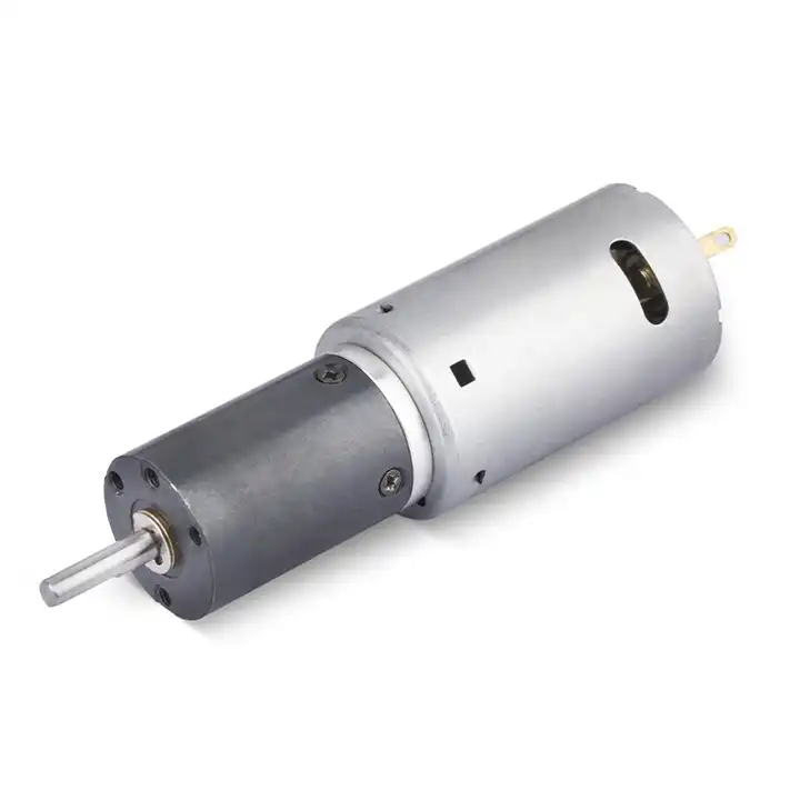
03. Peak torque has a time limit
Acceleration or breakaway events may require additional torque, but the driver, motor and gears each limit how long and how often peaks may occur. Use the measured output of the cyclic pick-and-place mechanism to challenge the proposed drive choice. Calculate the needed motion, account for efficiency where specified and check the physical shaft reaction. The objective to prevent transient torque specifications from masking a thermal overload can be achieved only if the motor, reduction unit and controller each remain inside their individual ratings. Confirm those boundaries using separate motor and gearbox allowable torque curves.
04. Starting friction can dominate small mechanisms
Seals, sliding guides and preloads make initial motion harder than established movement; measure breakaway with the final assembly. The practical question is what the cyclic pick-and-place mechanism asks the shaft to do during its hardest normal event. Capture the timing of starts and reversals and measure whether the current limit intervenes as intended. Review the failure condition in which stall torque is used to justify a repeated production cycle. A rated peak is meaningful only together with its allowed duration and the exact assembly to which it applies.
05. Calculate load-side rather than shaft-only torque
The lever arm, friction coefficient or process resistance must be translated to the gearbox output; do not infer duty from a motor wattage label. The cyclic pick-and-place mechanism can impose forces that a free gearmotor does not experience. Check the position of external supports, the coupling type and the path taken by mechanical reactions. Also look at cable routing through the intended motion range. A repeatable change after installation points toward a machine-interface issue that needs resolving at its source.
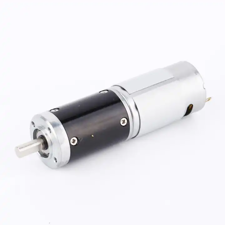
The design topic Calculate load-side rather than shaft-only torque also raises a question about the reduction unit used with the cyclic pick-and-place mechanism. For an overview of alternative arrangements, explore planetary gear reducer product overview. Reducer-only information must still be checked against the motor, driver and exact gearbox configuration considered for this application.
06. Read the motor and reducer tables independently
The smaller allowable value governs a given condition; a motor can be capable of more instantaneous torque than the gearbox should transmit. Qualify the proposed drive in the machine configuration that will actually be used. With the cyclic pick-and-place mechanism loaded, observe requested duty, mechanical clearance and operating condition using a controlled fixture and a signed dimensional inspection and retain the operating trace. Repeat the cycle long enough to expose a stable temperature trend where appropriate. The result must be assessed against agreed criteria, not against an informal impression that the motor feels satisfactory.
07. Apply a cycle-sensitive margin
If torque changes over time, document time at each level and validate against the supplier's thermal and fatigue methods. Create a stop-and-review rule for the cyclic pick-and-place mechanism that covers an undocumented assumption at the mechanical interface. Abnormal current, sound or motion requires isolating electrical causes from friction and mechanical damage. Preserve the measurement trace and inspect the interface; a stronger motor may conceal the symptom while exposing the gears or output bearings to higher force.
- Confirm the measurement basis for apply a cycle-sensitive margin, including instrument location and units.
- Record the normal and limiting operating states of the cyclic pick-and-place mechanism.
- Compare the observed load torque over time, acceleration peaks and their duration with verified assembly documentation before approving this configuration.
08. Record a peak-current trace
Log current and speed through starting, running and stopping; repeated peaks can identify a controller mismatch before mechanical damage appears. The final output is a measurable acceptance criterion for the cyclic pick-and-place mechanism, not just a catalog selection. Confirm that the drive can prevent transient torque specifications from masking a thermal overload during the complete intended cycle. Document the exact hardware revision, installation method and separate motor and gearbox allowable torque curves. This allows an incoming unit or later design change to be assessed on the same technical basis.

09. Numerical screening for cyclic pick-and-place mechanism
Consider a cyclic pick-and-place mechanism where the design task is to prevent transient torque specifications from masking a thermal overload. Imagine the selected mechanism repeats a four-second movement followed by a six-second dwell. A basic test can log output displacement, peak current and housing temperature for each ten-second cycle. This example defines a test method, not a product performance claim. After the arithmetic, mark the assumed quantities separately from load torque over time, acceleration peaks and their duration. A purchase specification should state which of those quantities came from machine measurements and which need confirmation through separate motor and gearbox allowable torque curves.
10. Verification procedure: load torque over time, acceleration peaks and their duration
The acceptance procedure for cyclic pick-and-place mechanism should begin with a configuration photograph, the wiring diagram and a measured mechanical baseline. Run the motion cycle while collecting load torque over time, acceleration peaks and their duration; retest after a representative warm period. Preserve evidence corresponding to separate motor and gearbox allowable torque curves, including deviations associated with stall torque is used to justify a repeated production cycle.
| Engineering checkpoint | Observation for cyclic pick-and-place mechanism | Approval implication |
|---|---|---|
| Machine duty | load torque over time, acceleration peaks and their duration | Keep the measured conditions of cyclic pick-and-place mechanism comparable |
| Output interface | Mounting and wiring of the cyclic pick-and-place mechanism | Check calculate load-side rather than shaft-only torque against the drawing |
| Evidence basis | separate motor and gearbox allowable torque curves | Confirms prevent transient torque specifications from masking a thermal overload |
| Escalation trigger | stall torque is used to justify a repeated production cycle | Stop for review if the cyclic pick-and-place mechanism behaves outside limits |
11. What to specify when quoting this selection task
To quote a geared motor for cyclic pick-and-place mechanism, define what motion is required, how much load changes and how often it starts. State the objective to prevent transient torque specifications from masking a thermal overload, document load torque over time, acceleration peaks and their duration, and provide connection and output-shaft details. Treat separate motor and gearbox allowable torque curves as a request for verifiable support rather than an assumed attribute.
- State the device and target: cyclic pick-and-place mechanism; prevent transient torque specifications from masking a thermal overload.
- Include locating pilot, shaft and flange tolerances for the cyclic pick-and-place mechanism installation.
- Identify voltage and feedback needed for the cyclic pick-and-place mechanism, including motor-driver protections.
- Connect load torque over time, acceleration peaks and their duration to peak and continuous load cases and relevant cycle timing.
- Record installation constraints for the cyclic pick-and-place mechanism and the planned acceptance method.
- Confirm separate motor and gearbox allowable torque curves before release of the exact motor-reducer option.
12. Release decision for cyclic pick-and-place mechanism
For cyclic pick-and-place mechanism, approving a gearmotor means showing evidence that it can prevent transient torque specifications from masking a thermal overload. Retain load torque over time, acceleration peaks and their duration and separate motor and gearbox allowable torque curves with the exact mounting and controller configuration. A later change in the machine that creates the condition where stall torque is used to justify a repeated production cycle invalidates the original acceptance assumption.
Questions raised by cyclic pick-and-place mechanism applications
Why is three torques belong on the review sheet important for this application?
Running, acceleration and stall-related values are not interchangeable; describe both magnitude and duration of each load event. In the cyclic pick-and-place mechanism, the review should link that condition to load torque over time, acceleration peaks and their duration before a motor is selected.
What mistake should be avoided when considering starting friction can dominate small mechanisms?
Seals, sliding guides and preloads make initial motion harder than established movement; measure breakaway with the final assembly. A failure to document the issue may lead to the situation where stall torque is used to justify a repeated production cycle.
How should apply a cycle-sensitive margin be checked?
If torque changes over time, document time at each level and validate against the supplier's thermal and fatigue methods. Collect evidence during the intended movement of the cyclic pick-and-place mechanism, not only while the output runs freely.
What records verify the cyclic pick-and-place mechanism drive configuration?
Provide the machine drawing, motor control requirements, load torque over time, acceleration peaks and their duration and separate motor and gearbox allowable torque curves. Explain the application goal: prevent transient torque specifications from masking a thermal overload.
To discuss prevent transient torque specifications from masking a thermal overload on a cyclic pick-and-place mechanism, send the measurement summary and interface drawing to [email protected]. Include the load torque over time, acceleration peaks and their duration so the motor and reduction unit can be assessed together.