The preferred option depends on the motion cycle, electrical controls and mechanical interface rather than one attractive product statistic. The example is a right-angle lifting adjustment module, with the specific goal to evaluate shaft geometry and safe holding behavior without assuming self-locking. This makes mounting envelope, shaft orientation, gear ratio and heat generation especially relevant. We examine mechanical load, electrical control and measurable acceptance evidence while guarding against the case where a worm gearbox is presumed to be a certified brake.
01. Compare shaft orientation first
Planetary gearheads commonly support coaxial layouts, while worm designs typically turn the drive through a right angle; machine space can dominate selection. The first calculation belongs to the machine rather than the motor. On the right-angle lifting adjustment module, locate the output load and describe its path through the coupling or shaft. Take account of startup and stopping as separate events. Then prepare a requirement sheet that explains what it means to evaluate shaft geometry and safe holding behavior without assuming self-locking; keep assumptions distinct from measured mechanical demands.
02. Treat backdriving as a design test
Some worm combinations resist backdrive under particular conditions, but vibration lubrication and wear can change that behavior. Do not blend bench readings with machine readings. The right-angle lifting adjustment module has a particular drive installation and mechanical resistance, so measure requested duty, mechanical clearance and operating condition with a controlled fixture and a signed dimensional inspection after the coupling is installed. Note test speed, load and ambient temperature. Compare results to the original expectation and investigate discrepancies before increasing the motor or gearbox size.
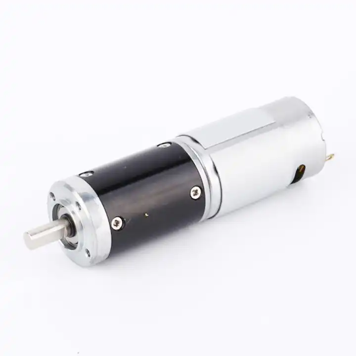
03. Evaluate losses at the operating point
Worm sliding contact can generate additional heat in some designs, yet actual comparison requires manufacturer efficiency and duty data. Use the measured output of the right-angle lifting adjustment module to challenge the proposed drive choice. Calculate the needed motion, account for efficiency where specified and check the physical shaft reaction. The objective to evaluate shaft geometry and safe holding behavior without assuming self-locking can be achieved only if the motor, reduction unit and controller each remain inside their individual ratings. Confirm those boundaries using verified backdrive and holding safety assessment.
04. Check intermittent holding requirements
A stationary vertical axis may still need a separate fail-safe brake and redundant structural protection. Startup, reversal and stopping are not interchangeable with continuous running. On the right-angle lifting adjustment module, identify how long each event lasts and how often it repeats. The credible failure scenario is that a worm gearbox is presumed to be a certified brake. Put the largest foreseeable transient in a separate line of the duty record; then verify that the controller and reduction stage are both suitable for its duration.
05. Consider alignment and coupling path
A right-angle gearbox can simplify layouts but change mounting reaction and service access; check the actual machine frame. The right-angle lifting adjustment module can impose forces that a free gearmotor does not experience. Check the position of external supports, the coupling type and the path taken by mechanical reactions. Also look at cable routing through the intended motion range. A repeatable change after installation points toward a machine-interface issue that needs resolving at its source.

06. Review input control strategy
Both motor types can be electrically controlled; braking current and stopping time depend on the motor drive and load inertia. A practical test plan for the right-angle lifting adjustment module specifies payload, mounting orientation, supply range and command timing before any result is recorded. Collect requested duty, mechanical clearance and operating condition by a controlled fixture and a signed dimensional inspection. After the initial functional run, repeat under the least favorable expected normal load. This provides evidence that can be compared with the proposed drive rating and with future incoming parts.
07. Do not infer precision from gear family
Backlash, stiffness and repeatability have model-specific values; ask for data under the required load direction. When the right-angle lifting adjustment module shows signs of a change in sound or free movement after installation, investigate before escalating the motor rating. Check whether the applied load, controller protection or shaft alignment has changed. One controlled change at a time reveals the likely cause more reliably than replacing several parts together. The engineering record should preserve the first abnormal measurement and the corrective action.
- Confirm the measurement basis for do not infer precision from gear family, including instrument location and units.
- Record the normal and limiting operating states of the right-angle lifting adjustment module.
- Compare the observed mounting envelope, shaft orientation, gear ratio and heat generation with verified assembly documentation before approving this configuration.
08. Compare life-cycle servicing
Lubricant heat exposure, seals and maintenance access may drive total cost more than the nominal purchase price. Finish with a decision that can be checked on the right-angle lifting adjustment module. The selected assembly must evaluate shaft geometry and safe holding behavior without assuming self-locking with the intended supply, installed load and duty pattern. Keep the approved interface drawing and verified backdrive and holding safety assessment alongside the test results. If a future machine revision alters those conditions, requalify the motor-and-reducer combination rather than assuming the earlier approval still applies.

09. Numerical screening for right-angle lifting adjustment module
Consider a right-angle lifting adjustment module where the design task is to evaluate shaft geometry and safe holding behavior without assuming self-locking. Imagine the selected mechanism repeats a four-second movement followed by a six-second dwell. A basic test can log output displacement, peak current and housing temperature for each ten-second cycle. This example defines a test method, not a product performance claim. After the arithmetic, mark the assumed quantities separately from mounting envelope, shaft orientation, gear ratio and heat generation. A purchase specification should state which of those quantities came from machine measurements and which need confirmation through verified backdrive and holding safety assessment.
10. Verification procedure: mounting envelope, shaft orientation, gear ratio and heat generation
The acceptance procedure for right-angle lifting adjustment module should begin with a configuration photograph, the wiring diagram and a measured mechanical baseline. Run the motion cycle while collecting mounting envelope, shaft orientation, gear ratio and heat generation; retest after a representative warm period. Preserve evidence corresponding to verified backdrive and holding safety assessment, including deviations associated with a worm gearbox is presumed to be a certified brake.
| Engineering checkpoint | Observation for right-angle lifting adjustment module | Approval implication |
|---|---|---|
| Machine duty | mounting envelope, shaft orientation, gear ratio and heat generation | Keep the measured conditions of right-angle lifting adjustment module comparable |
| Output interface | Mounting and wiring of the right-angle lifting adjustment module | Check consider alignment and coupling path against the drawing |
| Evidence basis | verified backdrive and holding safety assessment | Confirms evaluate shaft geometry and safe holding behavior without assuming self-locking |
| Escalation trigger | a worm gearbox is presumed to be a certified brake | Stop for review if the right-angle lifting adjustment module behaves outside limits |
11. What to specify when quoting this comparison task
To quote a geared motor for right-angle lifting adjustment module, define what motion is required, how much load changes and how often it starts. State the objective to evaluate shaft geometry and safe holding behavior without assuming self-locking, document mounting envelope, shaft orientation, gear ratio and heat generation, and provide connection and output-shaft details. Treat verified backdrive and holding safety assessment as a request for verifiable support rather than an assumed attribute.
- State the device and target: right-angle lifting adjustment module; evaluate shaft geometry and safe holding behavior without assuming self-locking.
- Include locating pilot, shaft and flange tolerances for the right-angle lifting adjustment module installation.
- Identify voltage and feedback needed for the right-angle lifting adjustment module, including motor-driver protections.
- Connect mounting envelope, shaft orientation, gear ratio and heat generation to peak and continuous load cases and relevant cycle timing.
- Record installation constraints for the right-angle lifting adjustment module and the planned acceptance method.
- Confirm verified backdrive and holding safety assessment before release of the exact motor-reducer option.
12. Release decision for right-angle lifting adjustment module
For right-angle lifting adjustment module, approving a gearmotor means showing evidence that it can evaluate shaft geometry and safe holding behavior without assuming self-locking. Retain mounting envelope, shaft orientation, gear ratio and heat generation and verified backdrive and holding safety assessment with the exact mounting and controller configuration. A later change in the machine that creates the condition where a worm gearbox is presumed to be a certified brake invalidates the original acceptance assumption.
Questions raised by right-angle lifting adjustment module applications
Why is compare shaft orientation first important for this application?
Planetary gearheads commonly support coaxial layouts, while worm designs typically turn the drive through a right angle; machine space can dominate selection. In the right-angle lifting adjustment module, the review should link that condition to mounting envelope, shaft orientation, gear ratio and heat generation before a motor is selected.
What mistake should be avoided when considering check intermittent holding requirements?
A stationary vertical axis may still need a separate fail-safe brake and redundant structural protection. A failure to document the issue may lead to the situation where a worm gearbox is presumed to be a certified brake.
How should do not infer precision from gear family be checked?
Backlash, stiffness and repeatability have model-specific values; ask for data under the required load direction. Collect evidence during the intended movement of the right-angle lifting adjustment module, not only while the output runs freely.
What records verify the right-angle lifting adjustment module drive configuration?
Provide the machine drawing, motor control requirements, mounting envelope, shaft orientation, gear ratio and heat generation and verified backdrive and holding safety assessment. Explain the application goal: evaluate shaft geometry and safe holding behavior without assuming self-locking.
To discuss evaluate shaft geometry and safe holding behavior without assuming self-locking on a right-angle lifting adjustment module, send the measurement summary and interface drawing to sprzedaż@planetarymotors.top. Include the mounting envelope, shaft orientation, gear ratio and heat generation so the motor and reduction unit can be assessed together.