The most expensive problems often arise at the interface between a healthy gearmotor and the machine around it. Consider a vertical adjustable platform that must decide whether loss of power requires an independent mechanical restraint. Its motor and reduction unit must be treated together with the supporting hardware and controller. The risk that gear reduction is assumed to prevent a vertical load from falling frames the checks in this article; gravity torque, static holding demand, brake-release delay and fault mode are part of the necessary evidence.
01. Start from the unpowered condition
Ask what the mechanism does when supply disappears or a wire breaks; a reduction gear is not automatically a safety-rated holding device. Treat the mechanism as a sequence of states, not a single rated speed. With the vertical adjustable platform, list the driven load, resistance at rest, available travel, and any gravity or process force. A suitable planetary gearmotor must serve the complete sequence. Only after that description is agreed should the target to decide whether loss of power requires an independent mechanical restraint be translated into electrical and mechanical specifications.
02. Calculate static gravity torque at the load
Mass, center of gravity and linkage radius set a holding demand that differs from motion acceleration torque. Define an instrumented check that another engineer can repeat on the vertical adjustable platform: use a torque instrument or a documented force-and-radius calculation to observe load torque, support reaction and operating speed, capture operating conditions and report uncertainty where it matters. The intended motion should be present during the trial. This approach can reveal a voltage-drop, alignment or loading issue that a free-running demonstration does not show.
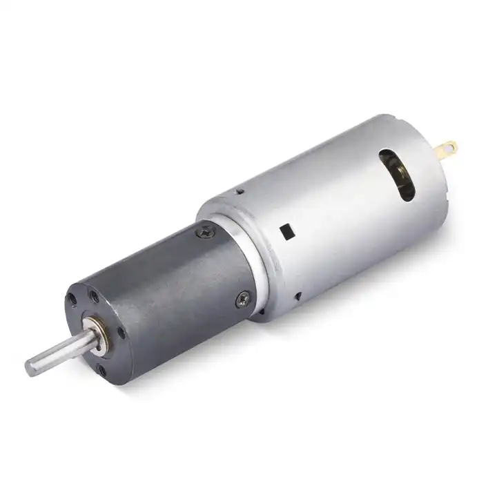
03. Differentiate holding and dynamic stopping
A brake intended to keep a stationary axis still may not safely absorb repeated emergency kinetic energy. At this point distinguish the requirement from the supplier rating. The vertical adjustable platform needs the objective to decide whether loss of power requires an independent mechanical restraint, but a motor-side number is not automatically a gearbox-output number. Account for the speed reduction and the actual load path. Use fail-safe brake assessment and safety review as the basis for comparing the proposed integrated gearmotor with the calculated machine demand.
04. Consider spring-applied power-release brakes
These can engage without energization, but suitability depends on exact brake specification, wiring and the required safety architecture. Assess transient loading on the vertical adjustable platform independently from the steady load. Momentum, breakaway friction and drive commands may create short peaks whose frequency determines the resulting heat and fatigue. The hazard to check is that gear reduction is assumed to prevent a vertical load from falling. Set current limits and stopping rules before any representative overload investigation.
05. Coordinate release timing with the controller
The drive may need to establish motor torque before the brake releases and settle before re-engagement to avoid sudden movement. Inspect the interface that connects the vertical adjustable platform to the gearmotor. Centering surfaces, bearing supports and connector clearance should correspond to the released drawing. Excessive coupling offset can load the output shaft even when calculated torque appears acceptable. Confirm the installed arrangement before changing the controller to compensate for unexpected behavior.
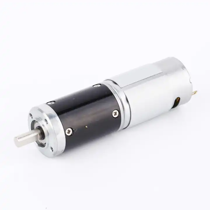
The design topic Coordinate release timing with the controller also raises a question about the reduction unit used with the vertical adjustable platform. For an overview of alternative arrangements, explore planetary drive arrangements. Reducer-only information must still be checked against the motor, driver and exact gearbox configuration considered for this application.
06. Check gearbox and coupling integrity
A motor-side brake cannot protect against a broken downstream shaft or key; analyze where the hazardous load is supported. For the vertical adjustable platform, write an acceptance procedure that can be run again after a design revision. The procedure should log speed-dependent sound, reversal play and mechanical alignment, measured through a controlled speed sweep and a repeatable lash or vibration measurement, together with software and wiring configuration. Observe both cold startup and a representative warm operating condition. Keep the outcome connected to the exact tested gearbox and motor revision.
07. Plan manual override safely
Maintenance release devices and rescue procedures must prevent uncontrolled motion and comply with machine-specific rules. When the vertical adjustable platform shows signs of an undocumented assumption at the mechanical interface, investigate before escalating the motor rating. Check whether the applied load, controller protection or shaft alignment has changed. One controlled change at a time reveals the likely cause more reliably than replacing several parts together. The engineering record should preserve the first abnormal measurement and the corrective action.
- Confirm the measurement basis for plan manual override safely, including instrument location and units.
- Record the normal and limiting operating states of the vertical adjustable platform.
- Compare the observed gravity torque, static holding demand, brake-release delay and fault mode with verified assembly documentation before approving this configuration.
08. Validate foreseeable faults
Test loss of supply, controller reset and commanded stop under supervised safe conditions before machine release. The final output is a measurable acceptance criterion for the vertical adjustable platform, not just a catalog selection. Confirm that the drive can decide whether loss of power requires an independent mechanical restraint during the complete intended cycle. Document the exact hardware revision, installation method and fail-safe brake assessment and safety review. This allows an incoming unit or later design change to be assessed on the same technical basis.
09. Numerical screening for vertical adjustable platform
The numerical exercise is deliberately not a product specification for a vertical adjustable platform. A 5 kg off-center load at a 0.10 m lever arm produces roughly 4.9 N m of static gravity torque using g = 9.81 m/s2. Dynamic loads and safety factors are additional; the example is not evidence of any brake or reducer capacity. Use it to frame gravity torque, static holding demand, brake-release delay and fault mode, and return to the aim to decide whether loss of power requires an independent mechanical restraint before selecting a gear ratio or controller. The load case must be checked using fail-safe brake assessment and safety review.
10. Verification procedure: gravity torque, static holding demand, brake-release delay and fault mode
To qualify a proposed geared motor on vertical adjustable platform, first verify dimensions and wiring against the signed drawing. Then test gravity torque, static holding demand, brake-release delay and fault mode during normal travel and the hardest foreseeable start. Keep fail-safe brake assessment and safety review with the instrument record. If the cycle exhibits a state where gear reduction is assumed to prevent a vertical load from falling, correct the configuration rather than normalizing the behavior.
| Engineering checkpoint | Observation for vertical adjustable platform | Approval implication |
|---|---|---|
| Machine duty | gravity torque, static holding demand, brake-release delay and fault mode | Keep the measured conditions of vertical adjustable platform comparable |
| Output interface | Mounting and wiring of the vertical adjustable platform | Check coordinate release timing with the controller against the drawing |
| Evidence basis | fail-safe brake assessment and safety review | Confirms decide whether loss of power requires an independent mechanical restraint |
| Escalation trigger | gear reduction is assumed to prevent a vertical load from falling | Stop for review if the vertical adjustable platform behaves outside limits |
11. What to specify when quoting this engineering task
Send a controlled specification for the vertical adjustable platform, including the installation drawing and driver type. Distinguish normal use from the risk that gear reduction is assumed to prevent a vertical load from falling. Offer gravity torque, static holding demand, brake-release delay and fault mode as the available measurement basis, while asking for fail-safe brake assessment and safety review on the actual offered configuration.
- State the device and target: vertical adjustable platform; decide whether loss of power requires an independent mechanical restraint.
- Include locating pilot, shaft and flange tolerances for the vertical adjustable platform installation.
- Identify voltage and feedback needed for the vertical adjustable platform, including motor-driver protections.
- Connect gravity torque, static holding demand, brake-release delay and fault mode to peak and continuous load cases and relevant cycle timing.
- Record installation constraints for the vertical adjustable platform and the planned acceptance method.
- Confirm fail-safe brake assessment and safety review before release of the exact motor-reducer option.
12. Release decision for vertical adjustable platform
The decision record for vertical adjustable platform should connect the objective to decide whether loss of power requires an independent mechanical restraint with the observed gravity torque, static holding demand, brake-release delay and fault mode. Compare each vendor option under the same working state and keep fail-safe brake assessment and safety review in the approved file. If design revisions introduce conditions where gear reduction is assumed to prevent a vertical load from falling, the selection needs a fresh review.
Questions raised by vertical adjustable platform applications
Why is start from the unpowered condition important for this application?
Ask what the mechanism does when supply disappears or a wire breaks; a reduction gear is not automatically a safety-rated holding device. In the vertical adjustable platform, the review should link that condition to gravity torque, static holding demand, brake-release delay and fault mode before a motor is selected.
What mistake should be avoided when considering consider spring-applied power-release brakes?
These can engage without energization, but suitability depends on exact brake specification, wiring and the required safety architecture. A failure to document the issue may lead to the situation where gear reduction is assumed to prevent a vertical load from falling.
How should plan manual override safely be checked?
Maintenance release devices and rescue procedures must prevent uncontrolled motion and comply with machine-specific rules. Collect evidence during the intended movement of the vertical adjustable platform, not only while the output runs freely.
What records verify the vertical adjustable platform drive configuration?
Provide the machine drawing, motor control requirements, gravity torque, static holding demand, brake-release delay and fault mode and fail-safe brake assessment and safety review. Explain the application goal: decide whether loss of power requires an independent mechanical restraint.
To discuss decide whether loss of power requires an independent mechanical restraint on a vertical adjustable platform, send the measurement summary and interface drawing to [email protected] (www.planetarymotors.top) എന്ന വിലാസത്തിൽ ബന്ധപ്പെടുക.. Include the gravity torque, static holding demand, brake-release delay and fault mode so the motor and reduction unit can be assessed together.