Engineering acceptance depends on the way a number is defined and measured, not only on its printed magnitude. Consider a bidirectional industrial indexer that must prevent mechanical fatigue during frequent reversal and abrupt stopping. Its motor and reduction unit must be treated together with the supporting hardware and controller. The risk that peak torque under reversal exceeds the stated nominal load frames the checks in this article; number of reversals, angular lash and acceleration torque peaks are part of the necessary evidence.
01. Distinguish reversal from constant rotation
Changing direction can unload one flank and reload another, introducing impact if backlash is crossed rapidly. For the bidirectional industrial indexer, sketch the motion path before looking at a product list. Mark the moving mass, friction points, external forces and positions where the mechanism can bind. Identify what happens just before motion starts and just after it ends. Those events often matter more than a nominal motor-power label when the goal is to prevent mechanical fatigue during frequent reversal and abrupt stopping.
02. Calculate deceleration as a torque event
Stopping a rotating inertia produces reaction torque that may exceed steady process torque; include downstream rotating mass. A useful engineering test captures load torque, support reaction and operating speed at the point where the requirement is applied. Use a torque instrument or a documented force-and-radius calculation and describe where the instrument is located. The bidirectional industrial indexer should be tested with its normal load attached. If a measured value differs from the initial calculation, reconcile the load model before treating that difference as a motor defect.
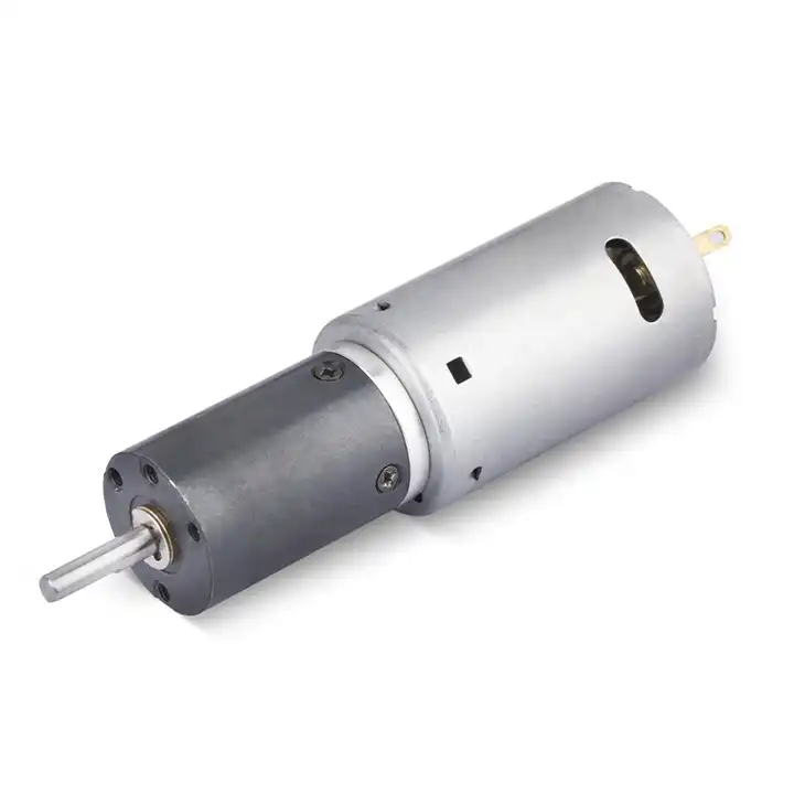
03. Control jerk and command timing
Smooth profiles reduce excitation and tooth impact, but overly slow ramps may conflict with cycle-time requirements. Translate the result into an output-side requirement for the bidirectional industrial indexer. A motor power figure, reduction ratio and shaft-load rating describe different things; none can replace the others. The operating load also depends on the mechanism and alignment. Check the selection against signed torque trace and endurance protocol and keep any unconfirmed value out of the approved production specification.
04. Assess load holding between moves
Gravity or external process force can backdrive an unpowered axis; specify the brake or mechanical restraint independently. Startup, reversal and stopping are not interchangeable with continuous running. On the bidirectional industrial indexer, identify how long each event lasts and how often it repeats. The credible failure scenario is that peak torque under reversal exceeds the stated nominal load. Put the largest foreseeable transient in a separate line of the duty record; then verify that the controller and reduction stage are both suitable for its duration.
05. Check the whole mechanical path
Couplings, keys, clamping hubs and output bearings can fail before internal planetary gears under sharp reversals. Mechanical integration is a separate qualification item on the bidirectional industrial indexer. Verify mounting pilot, flange seating, output-shaft support and strain relief before testing full load. A side load on the output bearing or an unaligned rigid coupling can change current and sound without any fault inside the motor. Inspect the final assembly drawing rather than relying on a catalog photograph.
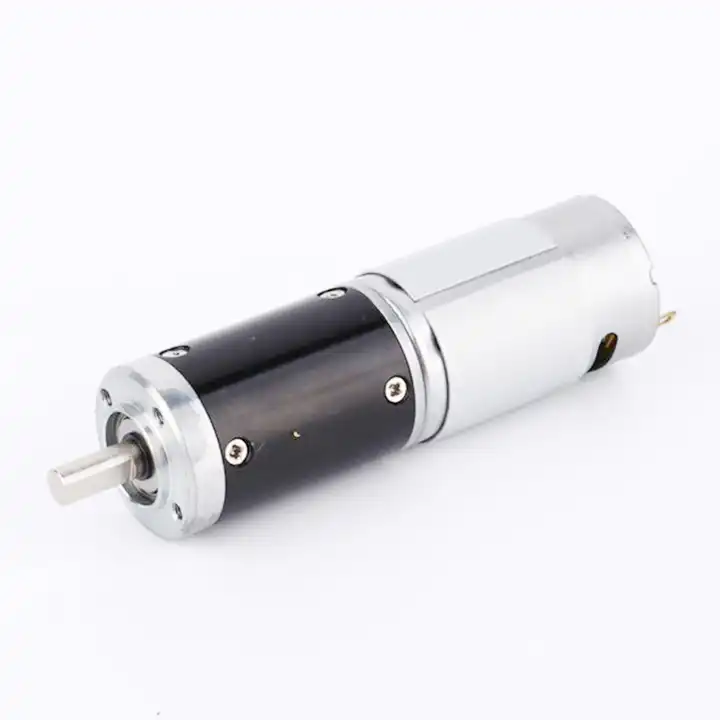
The design topic Check the whole mechanical path also raises a question about the reduction unit used with the bidirectional industrial indexer. For an overview of alternative arrangements, explore planetary gearbox configurations. Reducer-only information must still be checked against the motor, driver and exact gearbox configuration considered for this application.
06. Review motor-controller regeneration
Rapid slowing may return energy to the DC bus; the drive must have a safe way to manage voltage rise. The test record should explain what was connected and what was commanded on the bidirectional industrial indexer. Instrument actual output displacement, time and direction using an output tachometer, calibrated sensor or independent position gauge, then compare repeated trials at equivalent load and environmental conditions. If the reading drifts, investigate heat, drag and controller settings before selecting a replacement component. A reproducible result is worth more than an optimistic peak figure.
07. Track wear trends
Increased lost motion, current peaks or new impulsive sound after endurance cycling warrants inspection. The troubleshooting path for the bidirectional industrial indexer starts with the observation, not the part number. If an undocumented assumption at the mechanical interface is present, compare results before and after mechanical connection, provided that can be done safely. Recheck supply voltage and control commands, then investigate external load. Record which experiment changed the symptom and why.
- Confirm the measurement basis for track wear trends, including instrument location and units.
- Record the normal and limiting operating states of the bidirectional industrial indexer.
- Compare the observed number of reversals, angular lash and acceleration torque peaks with verified assembly documentation before approving this configuration.
08. Qualify with realistic direction changes
An endurance test must reproduce actual sign changes, dwell, torque and environment rather than equivalent hours of one-way running. Finish with a decision that can be checked on the bidirectional industrial indexer. The selected assembly must prevent mechanical fatigue during frequent reversal and abrupt stopping with the intended supply, installed load and duty pattern. Keep the approved interface drawing and signed torque trace and endurance protocol alongside the test results. If a future machine revision alters those conditions, requalify the motor-and-reducer combination rather than assuming the earlier approval still applies.

09. Numerical screening for bidirectional industrial indexer
Consider a bidirectional industrial indexer where the design task is to prevent mechanical fatigue during frequent reversal and abrupt stopping. Imagine the selected mechanism repeats a four-second movement followed by a six-second dwell. A basic test can log output displacement, peak current and housing temperature for each ten-second cycle. This example defines a test method, not a product performance claim. After the arithmetic, mark the assumed quantities separately from number of reversals, angular lash and acceleration torque peaks. A purchase specification should state which of those quantities came from machine measurements and which need confirmation through signed torque trace and endurance protocol.
10. Verification procedure: number of reversals, angular lash and acceleration torque peaks
The acceptance procedure for bidirectional industrial indexer should begin with a configuration photograph, the wiring diagram and a measured mechanical baseline. Run the motion cycle while collecting number of reversals, angular lash and acceleration torque peaks; retest after a representative warm period. Preserve evidence corresponding to signed torque trace and endurance protocol, including deviations associated with peak torque under reversal exceeds the stated nominal load.
| Engineering checkpoint | Observation for bidirectional industrial indexer | Approval implication |
|---|---|---|
| Machine duty | number of reversals, angular lash and acceleration torque peaks | Keep the measured conditions of bidirectional industrial indexer comparable |
| Output interface | Mounting and wiring of the bidirectional industrial indexer | Check check the whole mechanical path against the drawing |
| Evidence basis | signed torque trace and endurance protocol | Confirms prevent mechanical fatigue during frequent reversal and abrupt stopping |
| Escalation trigger | peak torque under reversal exceeds the stated nominal load | Stop for review if the bidirectional industrial indexer behaves outside limits |
11. What to specify when quoting this engineering task
To quote a geared motor for bidirectional industrial indexer, define what motion is required, how much load changes and how often it starts. State the objective to prevent mechanical fatigue during frequent reversal and abrupt stopping, document number of reversals, angular lash and acceleration torque peaks, and provide connection and output-shaft details. Treat signed torque trace and endurance protocol as a request for verifiable support rather than an assumed attribute.
- State the device and target: bidirectional industrial indexer; prevent mechanical fatigue during frequent reversal and abrupt stopping.
- Include locating pilot, shaft and flange tolerances for the bidirectional industrial indexer installation.
- Identify voltage and feedback needed for the bidirectional industrial indexer, including motor-driver protections.
- Connect number of reversals, angular lash and acceleration torque peaks to peak and continuous load cases and relevant cycle timing.
- Record installation constraints for the bidirectional industrial indexer and the planned acceptance method.
- Confirm signed torque trace and endurance protocol before release of the exact motor-reducer option.
12. Release decision for bidirectional industrial indexer
For bidirectional industrial indexer, approving a gearmotor means showing evidence that it can prevent mechanical fatigue during frequent reversal and abrupt stopping. Retain number of reversals, angular lash and acceleration torque peaks and signed torque trace and endurance protocol with the exact mounting and controller configuration. A later change in the machine that creates the condition where peak torque under reversal exceeds the stated nominal load invalidates the original acceptance assumption.
Questions raised by bidirectional industrial indexer applications
Why is distinguish reversal from constant rotation important for this application?
Changing direction can unload one flank and reload another, introducing impact if backlash is crossed rapidly. In the bidirectional industrial indexer, the review should link that condition to number of reversals, angular lash and acceleration torque peaks before a motor is selected.
What mistake should be avoided when considering assess load holding between moves?
Gravity or external process force can backdrive an unpowered axis; specify the brake or mechanical restraint independently. A failure to document the issue may lead to the situation where peak torque under reversal exceeds the stated nominal load.
How should track wear trends be checked?
Increased lost motion, current peaks or new impulsive sound after endurance cycling warrants inspection. Collect evidence during the intended movement of the bidirectional industrial indexer, not only while the output runs freely.
What records verify the bidirectional industrial indexer drive configuration?
Provide the machine drawing, motor control requirements, number of reversals, angular lash and acceleration torque peaks and signed torque trace and endurance protocol. Explain the application goal: prevent mechanical fatigue during frequent reversal and abrupt stopping.
To discuss prevent mechanical fatigue during frequent reversal and abrupt stopping on a bidirectional industrial indexer, send the measurement summary and interface drawing to [email protected] (www.planetarymotors.top) എന്ന വിലാസത്തിൽ ബന്ധപ്പെടുക.. Include the number of reversals, angular lash and acceleration torque peaks so the motor and reduction unit can be assessed together.