The most expensive problems often arise at the interface between a healthy gearmotor and the machine around it. The example is a bidirectional indexing table, with the specific goal to distinguish lost motion from encoder resolution and control error. This makes angular backlash, reversal hysteresis and positioning tolerance especially relevant. We examine mechanical load, electrical control and measurable acceptance evidence while guarding against the case where motor encoder counts are mistaken for output positioning precision.
01. Define backlash at the output
Tooth clearance allows a finite reverse movement before load transmission changes direction; the value must be stated with a measurement method. The first calculation belongs to the machine rather than the motor. On the bidirectional indexing table, locate the output load and describe its path through the coupling or shaft. Take account of startup and stopping as separate events. Then prepare a requirement sheet that explains what it means to distinguish lost motion from encoder resolution and control error; keep assumptions distinct from measured mechanical demands.
02. Separate repeatability from accuracy
An axis approaching every point from the same direction may repeat well even though bidirectional reversal reveals lost motion. Define an instrumented check that another engineer can repeat on the bidirectional indexing table: use a controlled fixture and a signed dimensional inspection to observe requested duty, mechanical clearance and operating condition, capture operating conditions and report uncertainty where it matters. The intended motion should be present during the trial. This approach can reveal a voltage-drop, alignment or loading issue that a free-running demonstration does not show.
03. Include torsional compliance
Elastic twist under load and clearance are different effects; high torque can add position deflection even after the gear teeth engage. Use the measured output of the bidirectional indexing table to challenge the proposed drive choice. Calculate the needed motion, account for efficiency where specified and check the physical shaft reaction. The objective to distinguish lost motion from encoder resolution and control error can be achieved only if the motor, reduction unit and controller each remain inside their individual ratings. Confirm those boundaries using loaded forward-reverse output position repeatability.
04. Locate the encoder thoughtfully
A motor-shaft encoder measures motor rotation and may not observe gearhead lash directly; output sensing changes the feedback boundary. Assess transient loading on the bidirectional indexing table independently from the steady load. Momentum, breakaway friction and drive commands may create short peaks whose frequency determines the resulting heat and fatigue. The hazard to check is that motor encoder counts are mistaken for output positioning precision. Set current limits and stopping rules before any representative overload investigation.
05. Reduce reversal errors at the motion planner
Approach direction, preload and compensation can improve a process, but software cannot restore absent mechanical stiffness. Before the bidirectional indexing table is assembled permanently, confirm tolerances and load support at its driven end. Fastening a motor securely does not guarantee that the rotating parts are coaxial. Examine the pilot, shaft fit and any pulley or lever arm, then record baseline current and sound before and after connection. This separates assembly-induced friction from component behavior.

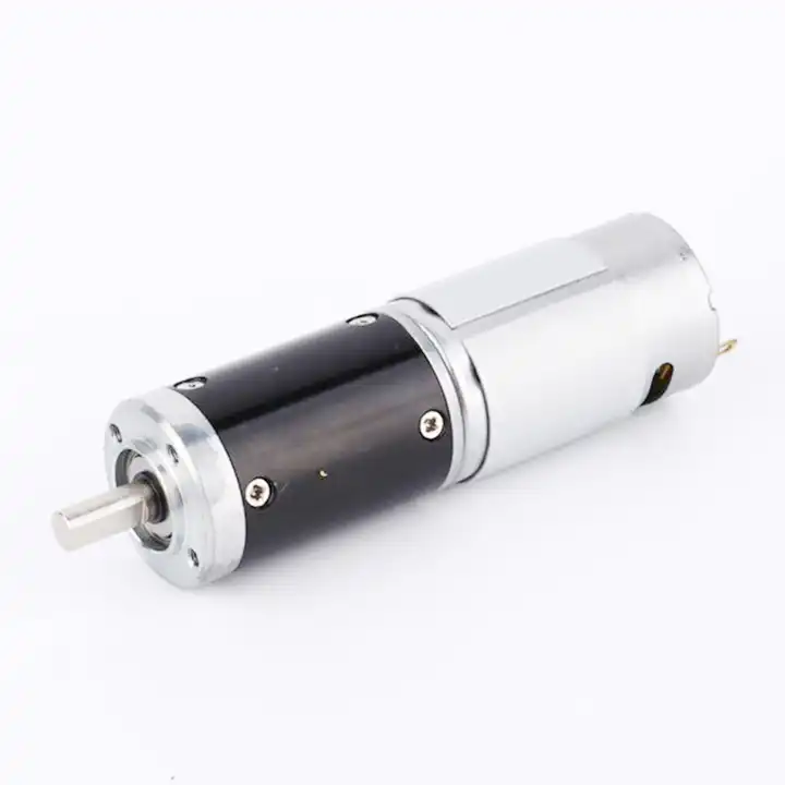
The design topic Reduce reversal errors at the motion planner also raises a question about the reduction unit used with the bidirectional indexing table. For an overview of alternative arrangements, explore planetary drive arrangements. Reducer-only information must still be checked against the motor, driver and exact gearbox configuration considered for this application.
06. Check load-side geometry
An angular error becomes a linear displacement at a radius; larger arms magnify small gearhead angular movements. A practical test plan for the bidirectional indexing table specifies payload, mounting orientation, supply range and command timing before any result is recorded. Collect load torque, support reaction and operating speed by a torque instrument or a documented force-and-radius calculation. After the initial functional run, repeat under the least favorable expected normal load. This provides evidence that can be compared with the proposed drive rating and with future incoming parts.
07. Test with a real load
Measure reversal using a dial indicator or suitable angular sensor while applying representative torque, not only by running an unloaded motor. When the bidirectional indexing table shows signs of a shaft load or transient torque outside the approved envelope, investigate before escalating the motor rating. Check whether the applied load, controller protection or shaft alignment has changed. One controlled change at a time reveals the likely cause more reliably than replacing several parts together. The engineering record should preserve the first abnormal measurement and the corrective action.
- Confirm the measurement basis for test with a real load, including instrument location and units.
- Record the normal and limiting operating states of the bidirectional indexing table.
- Compare the observed angular backlash, reversal hysteresis and positioning tolerance with verified assembly documentation before approving this configuration.
08. Specify practical acceptance criteria
State allowable positioning error at the tool or fixture, cycle direction and environmental condition in the RFQ. Close the engineering review by linking observed machine behavior to documented component limits. The bidirectional indexing table must distinguish lost motion from encoder resolution and control error without exceeding the ratings of its motor, gearhead or mechanical interfaces. Keep loaded forward-reverse output position repeatability with the relevant test report. Reopen the decision when the duty profile, applied load or wiring is changed.
09. Numerical screening for bidirectional indexing table
The numerical exercise is deliberately not a product specification for a bidirectional indexing table. For illustration, 0.5 degree of lost angular motion at an output arm radius of 100 mm corresponds to approximately 0.87 mm of arc travel. This geometric conversion does not predict the actual lash of a purchased motor. Use it to frame angular backlash, reversal hysteresis and positioning tolerance, and return to the aim to distinguish lost motion from encoder resolution and control error before selecting a gear ratio or controller. The load case must be checked using loaded forward-reverse output position repeatability.
10. Verification procedure: angular backlash, reversal hysteresis and positioning tolerance
To qualify a proposed geared motor on bidirectional indexing table, first verify dimensions and wiring against the signed drawing. Then test angular backlash, reversal hysteresis and positioning tolerance during normal travel and the hardest foreseeable start. Keep loaded forward-reverse output position repeatability with the instrument record. If the cycle exhibits a state where motor encoder counts are mistaken for output positioning precision, correct the configuration rather than normalizing the behavior.
| Engineering checkpoint | Observation for bidirectional indexing table | Approval implication |
|---|---|---|
| Machine duty | angular backlash, reversal hysteresis and positioning tolerance | Keep the measured conditions of bidirectional indexing table comparable |
| Output interface | Mounting and wiring of the bidirectional indexing table | Check reduce reversal errors at the motion planner against the drawing |
| Evidence basis | loaded forward-reverse output position repeatability | Confirms distinguish lost motion from encoder resolution and control error |
| Escalation trigger | motor encoder counts are mistaken for output positioning precision | Stop for review if the bidirectional indexing table behaves outside limits |
11. What to specify when quoting this engineering task
Send a controlled specification for the bidirectional indexing table, including the installation drawing and driver type. Distinguish normal use from the risk that motor encoder counts are mistaken for output positioning precision. Offer angular backlash, reversal hysteresis and positioning tolerance as the available measurement basis, while asking for loaded forward-reverse output position repeatability on the actual offered configuration.
- State the device and target: bidirectional indexing table; distinguish lost motion from encoder resolution and control error.
- Include locating pilot, shaft and flange tolerances for the bidirectional indexing table installation.
- Identify voltage and feedback needed for the bidirectional indexing table, including motor-driver protections.
- Connect angular backlash, reversal hysteresis and positioning tolerance to peak and continuous load cases and relevant cycle timing.
- Record installation constraints for the bidirectional indexing table and the planned acceptance method.
- Confirm loaded forward-reverse output position repeatability before release of the exact motor-reducer option.
12. Release decision for bidirectional indexing table
The decision record for bidirectional indexing table should connect the objective to distinguish lost motion from encoder resolution and control error with the observed angular backlash, reversal hysteresis and positioning tolerance. Compare each vendor option under the same working state and keep loaded forward-reverse output position repeatability in the approved file. If design revisions introduce conditions where motor encoder counts are mistaken for output positioning precision, the selection needs a fresh review.
Questions raised by bidirectional indexing table applications
Why is define backlash at the output important for this application?
Tooth clearance allows a finite reverse movement before load transmission changes direction; the value must be stated with a measurement method. In the bidirectional indexing table, the review should link that condition to angular backlash, reversal hysteresis and positioning tolerance before a motor is selected.
What mistake should be avoided when considering locate the encoder thoughtfully?
A motor-shaft encoder measures motor rotation and may not observe gearhead lash directly; output sensing changes the feedback boundary. A failure to document the issue may lead to the situation where motor encoder counts are mistaken for output positioning precision.
How should test with a real load be checked?
Measure reversal using a dial indicator or suitable angular sensor while applying representative torque, not only by running an unloaded motor. Collect evidence during the intended movement of the bidirectional indexing table, not only while the output runs freely.
What records verify the bidirectional indexing table drive configuration?
Provide the machine drawing, motor control requirements, angular backlash, reversal hysteresis and positioning tolerance and loaded forward-reverse output position repeatability. Explain the application goal: distinguish lost motion from encoder resolution and control error.
To discuss distinguish lost motion from encoder resolution and control error on a bidirectional indexing table, send the measurement summary and interface drawing to [email protected] (www.planetarymotors.top) എന്ന വിലാസത്തിൽ ബന്ധപ്പെടുക.. Include the angular backlash, reversal hysteresis and positioning tolerance so the motor and reduction unit can be assessed together.