The best reliability plan links service decisions to measured load, environment and operating history. The example is a repeated-cycle assembly machine, with the specific goal to design monitoring around credible failure mechanisms instead of an invented service-life promise. This makes running hours, accumulated cycles, current, sound and temperature drift especially relevant. We examine mechanical load, electrical control and measurable acceptance evidence while guarding against the case where a nominal life estimate ignores reversing overload and enclosure heat.
01. Define reliability around the actual mission
Hours running, cycle count and environmental conditions describe different stresses; quantify how long the machine must perform its function. Treat the mechanism as a sequence of states, not a single rated speed. With the repeated-cycle assembly machine, list the driven load, resistance at rest, available travel, and any gravity or process force. A suitable planetary gearmotor must serve the complete sequence. Only after that description is agreed should the target to design monitoring around credible failure mechanisms instead of an invented service-life promise be translated into electrical and mechanical specifications.
02. Understand gear tooth and bearing fatigue
Load peaks and the number of stress repetitions influence mechanical damage accumulation; average torque alone is incomplete. Do not blend bench readings with machine readings. The repeated-cycle assembly machine has a particular drive installation and mechanical resistance, so measure load torque, support reaction and operating speed with a torque instrument or a documented force-and-radius calculation after the coupling is installed. Note test speed, load and ambient temperature. Compare results to the original expectation and investigate discrepancies before increasing the motor or gearbox size.

03. Track lubricant health without unnecessary intervention
A sealed gearhead may be lifetime-filled for intended conditions; unexpected temperature or ingress changes the risk picture. Use the measured output of the repeated-cycle assembly machine to challenge the proposed drive choice. Calculate the needed motion, account for efficiency where specified and check the physical shaft reaction. The objective to design monitoring around credible failure mechanisms instead of an invented service-life promise can be achieved only if the motor, reduction unit and controller each remain inside their individual ratings. Confirm those boundaries using field log and duty-matched endurance validation.
04. Consider motor-side ageing
Brush wear in brushed variants, insulation stress, connector fretting and bearing wear can cause stoppages independent of gears. A successful single start does not validate a production cycle for the repeated-cycle assembly machine. Record the peak load, the length of the event and the interval before it recurs. The design review must specifically address the possibility that a nominal life estimate ignores reversing overload and enclosure heat. A protected repeat-cycle trial is more informative than repeating one unloaded startup.
05. Monitor leading indicators
Baseline current, acoustic signature, motion time and backlash trend allow early detection when measurement conditions are controlled. The repeated-cycle assembly machine can impose forces that a free gearmotor does not experience. Check the position of external supports, the coupling type and the path taken by mechanical reactions. Also look at cable routing through the intended motion range. A repeatable change after installation points toward a machine-interface issue that needs resolving at its source.
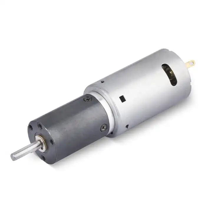
The design topic Monitor leading indicators also raises a question about the reduction unit used with the repeated-cycle assembly machine. For an overview of alternative arrangements, explore planetary gear reducer product overview. Reducer-only information must still be checked against the motor, driver and exact gearbox configuration considered for this application.
06. Review causes outside the gearbox
Misalignment, belt over-tension and software command shocks often create symptoms attributed to the gearmotor itself. Qualify the proposed drive in the machine configuration that will actually be used. With the repeated-cycle assembly machine loaded, observe speed-dependent sound, reversal play and mechanical alignment using a controlled speed sweep and a repeatable lash or vibration measurement and retain the operating trace. Repeat the cycle long enough to expose a stable temperature trend where appropriate. The result must be assessed against agreed criteria, not against an informal impression that the motor feels satisfactory.
07. Choose a meaningful accelerated test
Increased duty can change failure mechanisms, so an endurance plan should remain representative rather than merely harsher. The troubleshooting path for the repeated-cycle assembly machine starts with the observation, not the part number. If an undocumented assumption at the mechanical interface is present, compare results before and after mechanical connection, provided that can be done safely. Recheck supply voltage and control commands, then investigate external load. Record which experiment changed the symptom and why.
- Confirm the measurement basis for choose a meaningful accelerated test, including instrument location and units.
- Record the normal and limiting operating states of the repeated-cycle assembly machine.
- Compare the observed running hours, accumulated cycles, current, sound and temperature drift with verified assembly documentation before approving this configuration.
08. Close the field feedback loop
Record failure date, lot, environment, load history and repair findings so the next design revision addresses verified causes. For release on the repeated-cycle assembly machine, show evidence that the system can design monitoring around credible failure mechanisms instead of an invented service-life promise, including startup and stopping behavior. The approved record should state test conditions and contain field log and duty-matched endurance validation. Archive the motor, reduction unit and controller identification together so that a change of one part is not mistaken for the same qualified assembly.
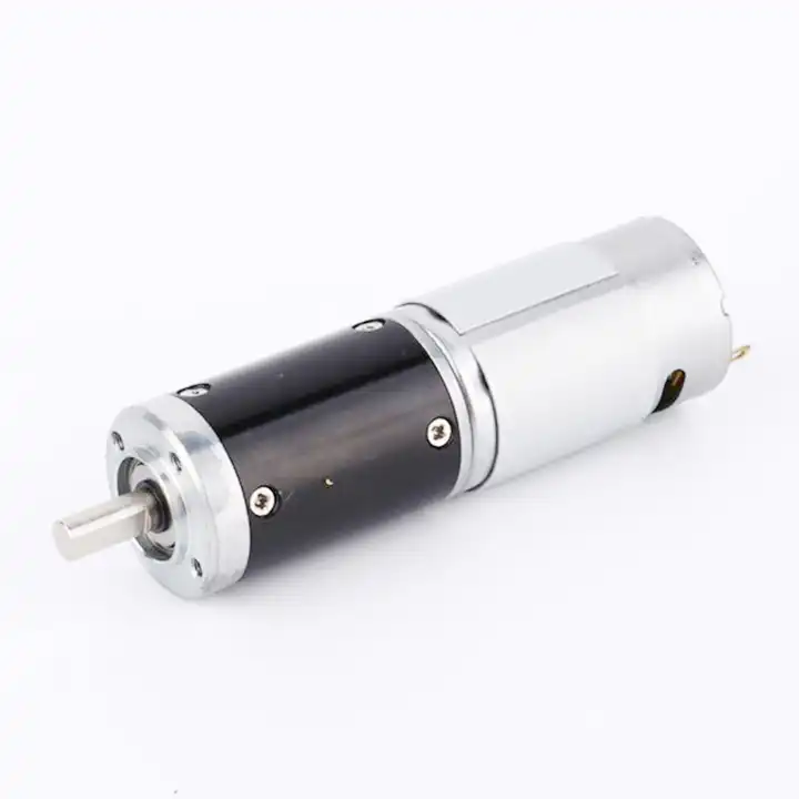
09. Numerical screening for repeated-cycle assembly machine
Consider a repeated-cycle assembly machine where the design task is to design monitoring around credible failure mechanisms instead of an invented service-life promise. Imagine the selected mechanism repeats a four-second movement followed by a six-second dwell. A basic test can log output displacement, peak current and housing temperature for each ten-second cycle. This example defines a test method, not a product performance claim. After the arithmetic, mark the assumed quantities separately from running hours, accumulated cycles, current, sound and temperature drift. A purchase specification should state which of those quantities came from machine measurements and which need confirmation through field log and duty-matched endurance validation.
10. Verification procedure: running hours, accumulated cycles, current, sound and temperature drift
The acceptance procedure for repeated-cycle assembly machine should begin with a configuration photograph, the wiring diagram and a measured mechanical baseline. Run the motion cycle while collecting running hours, accumulated cycles, current, sound and temperature drift; retest after a representative warm period. Preserve evidence corresponding to field log and duty-matched endurance validation, including deviations associated with a nominal life estimate ignores reversing overload and enclosure heat.
| Engineering checkpoint | Observation for repeated-cycle assembly machine | Approval implication |
|---|---|---|
| Machine duty | running hours, accumulated cycles, current, sound and temperature drift | Keep the measured conditions of repeated-cycle assembly machine comparable |
| Output interface | Mounting and wiring of the repeated-cycle assembly machine | Check monitor leading indicators against the drawing |
| Evidence basis | field log and duty-matched endurance validation | Confirms design monitoring around credible failure mechanisms instead of an invented service-life promise |
| Escalation trigger | a nominal life estimate ignores reversing overload and enclosure heat | Stop for review if the repeated-cycle assembly machine behaves outside limits |
11. What to specify when quoting this maintenance task
To quote a geared motor for repeated-cycle assembly machine, define what motion is required, how much load changes and how often it starts. State the objective to design monitoring around credible failure mechanisms instead of an invented service-life promise, document running hours, accumulated cycles, current, sound and temperature drift, and provide connection and output-shaft details. Treat field log and duty-matched endurance validation as a request for verifiable support rather than an assumed attribute.
- State the device and target: repeated-cycle assembly machine; design monitoring around credible failure mechanisms instead of an invented service-life promise.
- Include locating pilot, shaft and flange tolerances for the repeated-cycle assembly machine installation.
- Identify voltage and feedback needed for the repeated-cycle assembly machine, including motor-driver protections.
- Connect running hours, accumulated cycles, current, sound and temperature drift to peak and continuous load cases and relevant cycle timing.
- Record installation constraints for the repeated-cycle assembly machine and the planned acceptance method.
- Confirm field log and duty-matched endurance validation before release of the exact motor-reducer option.
12. Release decision for repeated-cycle assembly machine
For repeated-cycle assembly machine, approving a gearmotor means showing evidence that it can design monitoring around credible failure mechanisms instead of an invented service-life promise. Retain running hours, accumulated cycles, current, sound and temperature drift and field log and duty-matched endurance validation with the exact mounting and controller configuration. A later change in the machine that creates the condition where a nominal life estimate ignores reversing overload and enclosure heat invalidates the original acceptance assumption.
Questions raised by repeated-cycle assembly machine applications
Why is define reliability around the actual mission important for this application?
Hours running, cycle count and environmental conditions describe different stresses; quantify how long the machine must perform its function. In the repeated-cycle assembly machine, the review should link that condition to running hours, accumulated cycles, current, sound and temperature drift before a motor is selected.
What mistake should be avoided when considering consider motor-side ageing?
Brush wear in brushed variants, insulation stress, connector fretting and bearing wear can cause stoppages independent of gears. A failure to document the issue may lead to the situation where a nominal life estimate ignores reversing overload and enclosure heat.
How should choose a meaningful accelerated test be checked?
Increased duty can change failure mechanisms, so an endurance plan should remain representative rather than merely harsher. Collect evidence during the intended movement of the repeated-cycle assembly machine, not only while the output runs freely.
What records verify the repeated-cycle assembly machine drive configuration?
Provide the machine drawing, motor control requirements, running hours, accumulated cycles, current, sound and temperature drift and field log and duty-matched endurance validation. Explain the application goal: design monitoring around credible failure mechanisms instead of an invented service-life promise.
To discuss design monitoring around credible failure mechanisms instead of an invented service-life promise on a repeated-cycle assembly machine, send the measurement summary and interface drawing to [email protected] (www.planetarymotors.top) എന്ന വിലാസത്തിൽ ബന്ധപ്പെടുക.. Include the running hours, accumulated cycles, current, sound and temperature drift so the motor and reduction unit can be assessed together.