Engineering acceptance depends on the way a number is defined and measured, not only on its printed magnitude. Consider a closed-loop valve actuator that must turn motor-side encoder pulses into useful output measurement with error awareness. Its motor and reduction unit must be treated together with the supporting hardware and controller. The risk that encoder resolution is advertised as guaranteed output accuracy frames the checks in this article; encoder counts per revolution, decoding method, reduction ratio and backlash are part of the necessary evidence.
01. Locate the sensor in the drivetrain
An encoder at the motor shaft observes a different mechanical state from a sensor after the reduction gear; backlash can hide output movement. The first calculation belongs to the machine rather than the motor. On the closed-loop valve actuator, locate the output load and describe its path through the coupling or shaft. Take account of startup and stopping as separate events. Then prepare a requirement sheet that explains what it means to turn motor-side encoder pulses into useful output measurement with error awareness; keep assumptions distinct from measured mechanical demands.
02. Clarify counts and pulses terminology
Manufacturers may specify cycles per channel, pulses per revolution or decoded counts; the controller must use the matching definition. Set up one repeatable operating point on the closed-loop valve actuator. Record the applied load and supply conditions, then collect requested duty, mechanical clearance and operating condition. The practical measurement method is a controlled fixture and a signed dimensional inspection; retain a trace rather than only a pass/fail statement. This distinguishes a controller limit from resistance in the attached mechanism and makes later comparisons between candidates meaningful.

03. Calculate nominal output counts
If the gear ratio is known, the motor-side count per revolution scales by that ratio, but this does not eliminate lost motion. Use the measured output of the closed-loop valve actuator to challenge the proposed drive choice. Calculate the needed motion, account for efficiency where specified and check the physical shaft reaction. The objective to turn motor-side encoder pulses into useful output measurement with error awareness can be achieved only if the motor, reduction unit and controller each remain inside their individual ratings. Confirm those boundaries using independent output-position calibration.
04. Respect direction and polarity
Channel order determines forward and reverse counting; wiring errors can cause feedback loops to accelerate in the wrong direction. A successful single start does not validate a production cycle for the closed-loop valve actuator. Record the peak load, the length of the event and the interval before it recurs. The design review must specifically address the possibility that encoder resolution is advertised as guaranteed output accuracy. A protected repeat-cycle trial is more informative than repeating one unloaded startup.
05. Choose the right reference strategy
Incremental encoders require homing or stored state, while absolute position sensing may provide an external reference after power loss. Before the closed-loop valve actuator is assembled permanently, confirm tolerances and load support at its driven end. Fastening a motor securely does not guarantee that the rotating parts are coaxial. Examine the pilot, shaft fit and any pulley or lever arm, then record baseline current and sound before and after connection. This separates assembly-induced friction from component behavior.
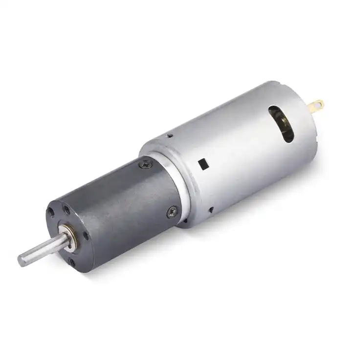
The design topic Choose the right reference strategy also raises a question about the reduction unit used with the closed-loop valve actuator. For an overview of alternative arrangements, explore planetary drive arrangements. Reducer-only information must still be checked against the motor, driver and exact gearbox configuration considered for this application.
06. Protect the signal in a motor harness
Current switching noise and long cables can cause missed counts; shielding, grounding and line drivers depend on the electrical design. Qualify the proposed drive in the machine configuration that will actually be used. With the closed-loop valve actuator loaded, observe requested duty, mechanical clearance and operating condition using a controlled fixture and a signed dimensional inspection and retain the operating trace. Repeat the cycle long enough to expose a stable temperature trend where appropriate. The result must be assessed against agreed criteria, not against an informal impression that the motor feels satisfactory.
07. Calibrate under mechanical load
Measure a full forward and reverse traverse at the actual output with an independent instrument to quantify real repeatability. When the closed-loop valve actuator shows signs of a shaft load or transient torque outside the approved envelope, investigate before escalating the motor rating. Check whether the applied load, controller protection or shaft alignment has changed. One controlled change at a time reveals the likely cause more reliably than replacing several parts together. The engineering record should preserve the first abnormal measurement and the corrective action.
- Confirm the measurement basis for calibrate under mechanical load, including instrument location and units.
- Record the normal and limiting operating states of the closed-loop valve actuator.
- Compare the observed encoder counts per revolution, decoding method, reduction ratio and backlash with verified assembly documentation before approving this configuration.
08. Plan fault detection
Stalled output, slipping couplings and encoder disconnection should create detectable faults rather than silent motion commands. Finish with a decision that can be checked on the closed-loop valve actuator. The selected assembly must turn motor-side encoder pulses into useful output measurement with error awareness with the intended supply, installed load and duty pattern. Keep the approved interface drawing and independent output-position calibration alongside the test results. If a future machine revision alters those conditions, requalify the motor-and-reducer combination rather than assuming the earlier approval still applies.
09. Numerical screening for closed-loop valve actuator
The numerical exercise is deliberately not a product specification for a closed-loop valve actuator. Suppose an incremental encoder provides 12 electrical cycles per motor revolution, the controller decodes four edges per cycle and the gear ratio is 30:1. The nominal total is 12 x 4 x 30 = 1,440 decoded counts per output revolution. Actual output accuracy still includes backlash and compliance. Use it to frame encoder counts per revolution, decoding method, reduction ratio and backlash, and return to the aim to turn motor-side encoder pulses into useful output measurement with error awareness before selecting a gear ratio or controller. The load case must be checked using independent output-position calibration.
10. Verification procedure: encoder counts per revolution, decoding method, reduction ratio and backlash
To qualify a proposed geared motor on closed-loop valve actuator, first verify dimensions and wiring against the signed drawing. Then test encoder counts per revolution, decoding method, reduction ratio and backlash during normal travel and the hardest foreseeable start. Keep independent output-position calibration with the instrument record. If the cycle exhibits a state where encoder resolution is advertised as guaranteed output accuracy, correct the configuration rather than normalizing the behavior.
| Engineering checkpoint | Observation for closed-loop valve actuator | Approval implication |
|---|---|---|
| Machine duty | encoder counts per revolution, decoding method, reduction ratio and backlash | Keep the measured conditions of closed-loop valve actuator comparable |
| Output interface | Mounting and wiring of the closed-loop valve actuator | Check choose the right reference strategy against the drawing |
| Evidence basis | independent output-position calibration | Confirms turn motor-side encoder pulses into useful output measurement with error awareness |
| Escalation trigger | encoder resolution is advertised as guaranteed output accuracy | Stop for review if the closed-loop valve actuator behaves outside limits |
11. What to specify when quoting this engineering task
Send a controlled specification for the closed-loop valve actuator, including the installation drawing and driver type. Distinguish normal use from the risk that encoder resolution is advertised as guaranteed output accuracy. Offer encoder counts per revolution, decoding method, reduction ratio and backlash as the available measurement basis, while asking for independent output-position calibration on the actual offered configuration.
- State the device and target: closed-loop valve actuator; turn motor-side encoder pulses into useful output measurement with error awareness.
- Include locating pilot, shaft and flange tolerances for the closed-loop valve actuator installation.
- Identify voltage and feedback needed for the closed-loop valve actuator, including motor-driver protections.
- Connect encoder counts per revolution, decoding method, reduction ratio and backlash to peak and continuous load cases and relevant cycle timing.
- Record installation constraints for the closed-loop valve actuator and the planned acceptance method.
- Confirm independent output-position calibration before release of the exact motor-reducer option.
12. Release decision for closed-loop valve actuator
The decision record for closed-loop valve actuator should connect the objective to turn motor-side encoder pulses into useful output measurement with error awareness with the observed encoder counts per revolution, decoding method, reduction ratio and backlash. Compare each vendor option under the same working state and keep independent output-position calibration in the approved file. If design revisions introduce conditions where encoder resolution is advertised as guaranteed output accuracy, the selection needs a fresh review.
Questions raised by closed-loop valve actuator applications
Why is locate the sensor in the drivetrain important for this application?
An encoder at the motor shaft observes a different mechanical state from a sensor after the reduction gear; backlash can hide output movement. In the closed-loop valve actuator, the review should link that condition to encoder counts per revolution, decoding method, reduction ratio and backlash before a motor is selected.
What mistake should be avoided when considering respect direction and polarity?
Channel order determines forward and reverse counting; wiring errors can cause feedback loops to accelerate in the wrong direction. A failure to document the issue may lead to the situation where encoder resolution is advertised as guaranteed output accuracy.
How should calibrate under mechanical load be checked?
Measure a full forward and reverse traverse at the actual output with an independent instrument to quantify real repeatability. Collect evidence during the intended movement of the closed-loop valve actuator, not only while the output runs freely.
What records verify the closed-loop valve actuator drive configuration?
Provide the machine drawing, motor control requirements, encoder counts per revolution, decoding method, reduction ratio and backlash and independent output-position calibration. Explain the application goal: turn motor-side encoder pulses into useful output measurement with error awareness.
To discuss turn motor-side encoder pulses into useful output measurement with error awareness on a closed-loop valve actuator, send the measurement summary and interface drawing to [email protected] (www.planetarymotors.top) എന്ന വിലാസത്തിൽ ബന്ധപ്പെടുക.. Include the encoder counts per revolution, decoding method, reduction ratio and backlash so the motor and reduction unit can be assessed together.