Engineering acceptance depends on the way a number is defined and measured, not only on its printed magnitude. Consider a receiving inspection bench that must turn purchase requirements into repeatable acceptance evidence. Its motor and reduction unit must be treated together with the supporting hardware and controller. The risk that parts pass visual inspection but fail loaded operation frames the checks in this article; model identity, fitted dimensions, no-load current and loaded torque are part of the necessary evidence.
01. Begin with traceability and identity
Confirm ordered configuration, labels, drawing revision and matching connector or shaft options before energizing any sample. For the receiving inspection bench, sketch the motion path before looking at a product list. Mark the moving mass, friction points, external forces and positions where the mechanism can bind. Identify what happens just before motion starts and just after it ends. Those events often matter more than a nominal motor-power label when the goal is to turn purchase requirements into repeatable acceptance evidence.
02. Inspect mounting and shaft geometry
Measure critical overall length, locating pilot, bolt-circle features and output shaft interface with controlled instruments. A useful engineering test captures load torque, support reaction and operating speed at the point where the requirement is applied. Use a torque instrument or a documented force-and-radius calculation and describe where the instrument is located. The receiving inspection bench should be tested with its normal load attached. If a measured value differs from the initial calculation, reconcile the load model before treating that difference as a motor defect.
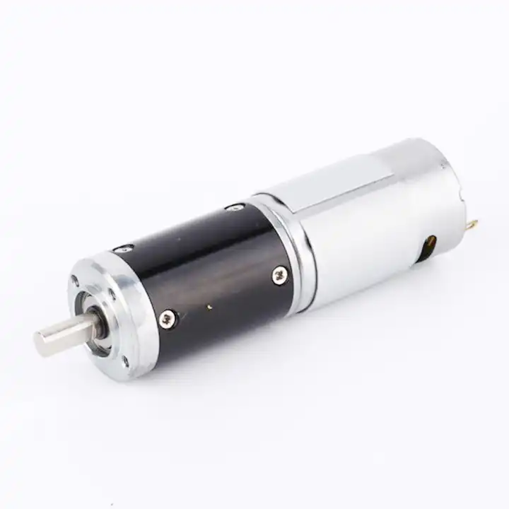
03. Measure no-load behavior correctly
Record terminal voltage, speed, current, direction and sound at a stated ambient condition; avoid comparing unrelated supply settings. Use the measured output of the receiving inspection bench to challenge the proposed drive choice. Calculate the needed motion, account for efficiency where specified and check the physical shaft reaction. The objective to turn purchase requirements into repeatable acceptance evidence can be achieved only if the motor, reduction unit and controller each remain inside their individual ratings. Confirm those boundaries using first article inspection and lot sampling record.
04. Create a safe loaded operating point
Use an instrumented brake or fixture within approved ratings to check output speed, electrical current and torque simultaneously. Startup, reversal and stopping are not interchangeable with continuous running. On the receiving inspection bench, identify how long each event lasts and how often it repeats. The credible failure scenario is that parts pass visual inspection but fail loaded operation. Put the largest foreseeable transient in a separate line of the duty record; then verify that the controller and reduction stage are both suitable for its duration.
05. Define backlash and play methods
Measurement torque and displacement direction affect readings; specify a repeatable method for angular lash and axial/radial play. Mechanical integration is a separate qualification item on the receiving inspection bench. Verify mounting pilot, flange seating, output-shaft support and strain relief before testing full load. A side load on the output bearing or an unaligned rigid coupling can change current and sound without any fault inside the motor. Inspect the final assembly drawing rather than relying on a catalog photograph.

The design topic Define backlash and play methods also raises a question about the reduction unit used with the receiving inspection bench. For an overview of alternative arrangements, explore industrial planetary gearbox applications. Reducer-only information must still be checked against the motor, driver and exact gearbox configuration considered for this application.
06. Check thermal response
Run an agreed duty cycle long enough to observe temperature stabilization or trend, while respecting specified limits. A practical test plan for the receiving inspection bench specifies payload, mounting orientation, supply range and command timing before any result is recorded. Collect cycle duration, case temperature and surrounding air temperature by a repeatable duty-cycle test with temperature logging. After the initial functional run, repeat under the least favorable expected normal load. This provides evidence that can be compared with the proposed drive rating and with future incoming parts.
07. Inspect electrical integrity
Where applicable verify continuity, insulation, connector polarity and sensor output according to the approved technical documentation. Create a stop-and-review rule for the receiving inspection bench that covers an electrical limit or an unexpected controller reset. Abnormal current, sound or motion requires isolating electrical causes from friction and mechanical damage. Preserve the measurement trace and inspect the interface; a stronger motor may conceal the symptom while exposing the gears or output bearings to higher force.
- Confirm the measurement basis for inspect electrical integrity, including instrument location and units.
- Record the normal and limiting operating states of the receiving inspection bench.
- Compare the observed model identity, fitted dimensions, no-load current and loaded torque with verified assembly documentation before approving this configuration.
08. Record failures without retesting away evidence
Isolate outliers, save photographs and traces, and distinguish sampling decisions from a claim that every production unit passed. For release on the receiving inspection bench, show evidence that the system can turn purchase requirements into repeatable acceptance evidence, including startup and stopping behavior. The approved record should state test conditions and contain first article inspection and lot sampling record. Archive the motor, reduction unit and controller identification together so that a change of one part is not mistaken for the same qualified assembly.
09. Numerical screening for receiving inspection bench
The numerical exercise is deliberately not a product specification for a receiving inspection bench. Imagine the selected mechanism repeats a four-second movement followed by a six-second dwell. A basic test can log output displacement, peak current and housing temperature for each ten-second cycle. This example defines a test method, not a product performance claim. Use it to frame model identity, fitted dimensions, no-load current and loaded torque, and return to the aim to turn purchase requirements into repeatable acceptance evidence before selecting a gear ratio or controller. The load case must be checked using first article inspection and lot sampling record.
10. Verification procedure: model identity, fitted dimensions, no-load current and loaded torque
To qualify a proposed geared motor on receiving inspection bench, first verify dimensions and wiring against the signed drawing. Then test model identity, fitted dimensions, no-load current and loaded torque during normal travel and the hardest foreseeable start. Keep first article inspection and lot sampling record with the instrument record. If the cycle exhibits a state where parts pass visual inspection but fail loaded operation, correct the configuration rather than normalizing the behavior.
| Engineering checkpoint | Observation for receiving inspection bench | Approval implication |
|---|---|---|
| Machine duty | model identity, fitted dimensions, no-load current and loaded torque | Keep the measured conditions of receiving inspection bench comparable |
| Output interface | Mounting and wiring of the receiving inspection bench | Check define backlash and play methods against the drawing |
| Evidence basis | first article inspection and lot sampling record | Confirms turn purchase requirements into repeatable acceptance evidence |
| Escalation trigger | parts pass visual inspection but fail loaded operation | Stop for review if the receiving inspection bench behaves outside limits |
11. What to specify when quoting this engineering task
Send a controlled specification for the receiving inspection bench, including the installation drawing and driver type. Distinguish normal use from the risk that parts pass visual inspection but fail loaded operation. Offer model identity, fitted dimensions, no-load current and loaded torque as the available measurement basis, while asking for first article inspection and lot sampling record on the actual offered configuration.
- State the device and target: receiving inspection bench; turn purchase requirements into repeatable acceptance evidence.
- Include locating pilot, shaft and flange tolerances for the receiving inspection bench installation.
- Identify voltage and feedback needed for the receiving inspection bench, including motor-driver protections.
- Connect model identity, fitted dimensions, no-load current and loaded torque to peak and continuous load cases and relevant cycle timing.
- Record installation constraints for the receiving inspection bench and the planned acceptance method.
- Confirm first article inspection and lot sampling record before release of the exact motor-reducer option.
12. Release decision for receiving inspection bench
The decision record for receiving inspection bench should connect the objective to turn purchase requirements into repeatable acceptance evidence with the observed model identity, fitted dimensions, no-load current and loaded torque. Compare each vendor option under the same working state and keep first article inspection and lot sampling record in the approved file. If design revisions introduce conditions where parts pass visual inspection but fail loaded operation, the selection needs a fresh review.
Questions raised by receiving inspection bench applications
Why is begin with traceability and identity important for this application?
Confirm ordered configuration, labels, drawing revision and matching connector or shaft options before energizing any sample. In the receiving inspection bench, the review should link that condition to model identity, fitted dimensions, no-load current and loaded torque before a motor is selected.
What mistake should be avoided when considering create a safe loaded operating point?
Use an instrumented brake or fixture within approved ratings to check output speed, electrical current and torque simultaneously. A failure to document the issue may lead to the situation where parts pass visual inspection but fail loaded operation.
How should inspect electrical integrity be checked?
Where applicable verify continuity, insulation, connector polarity and sensor output according to the approved technical documentation. Collect evidence during the intended movement of the receiving inspection bench, not only while the output runs freely.
What records verify the receiving inspection bench drive configuration?
Provide the machine drawing, motor control requirements, model identity, fitted dimensions, no-load current and loaded torque and first article inspection and lot sampling record. Explain the application goal: turn purchase requirements into repeatable acceptance evidence.
To discuss turn purchase requirements into repeatable acceptance evidence on a receiving inspection bench, send the measurement summary and interface drawing to [email protected]. Include the model identity, fitted dimensions, no-load current and loaded torque so the motor and reduction unit can be assessed together.